|
Do you want to be a better CNC'er in 37 Seconds? Get Better Tool Life, Surface Finish, and Material Removal Rates Fast. It's that easy. You can install and get results now. |
4th Axis for the IH CNC Mill
Design Notes
Really the first decision to make designing a fourth axis is whether you plan to build it around a rotary table with its associated worm gearing or not. Taking that approach is probably the fastest and easiest route, but it will have a shortcoming, and that is backlash. The worm gears in import rotabs may actually have quite a bit of backlash. You can try to adjust it out, and often that results in binding, which can be overcome with a honking big motor, but which will eventually wear out your worm. In the meanwhile, rapid wear will keep you busy readjusting it frequently.
The fancier approach is to use a Harmonic Drive. These are zero backlash devices invented back in the 50's for Defense applications. They're common in CNC and robotics, because they are compact and can have pretty high drive ratios. The other approach one could take is to either direct drive, or use a timing gear pulley setup such as you would often use to gear down the X, Y, or Z axes. I've seen really cool 4th axis setups built in this way out of spindexers or even small lathe headstocks, as well as from scratch.
Since there are a lot of trade offs flying around, I put together a quick calculator in Excel that you can download to do some back of the envelope calculations for the 4th axis. It looks like this:
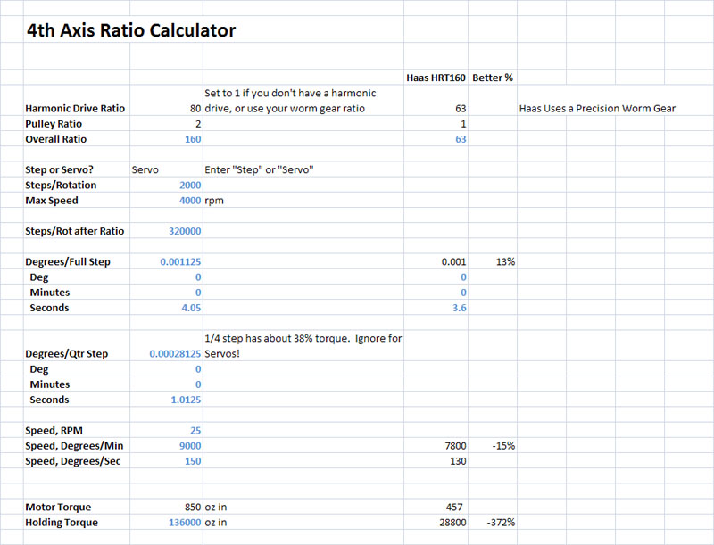
Avoid messing with the blue numbers, they're formulas. Instead, enter your drive ratio for either a Harmonic Drive or the worm gear setup on your rotab, any additional timing pulley ratio, whether you will use a Step or Servo motor, and lastly the motor's torque. The calculator will do the rest and will even let you compare your design to a Haas HRT160 indexer. The numbers I show in the example above represent the design I will likely follow for my own project. I snagged some 80:1 ratio Harmonic Drives on eBay that are brand new:
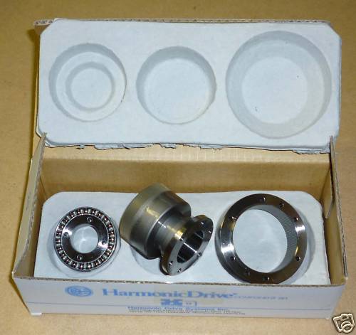
Harmonic Drive Systems CSF-20-80-2A-GR-SP NEW IN BOX!
I bought two of these units. They were not cheap, but not really egregious either and a Harmonic Drive is just the ticket for a really slick 4th axis. It would be cheaper to use a step motor, so I am still dithering about that, but the engineering calcs show a servo. Performance if I apply an additional 2:1 reduction with a timing pulley setup will be pretty comparable to the Haas. There's oodles of holding torque available with the high drive ratio and the big servo, so I don't know if it is worth adding a brake. I'll probably set up the design to accomodate one and then wait to see if it is needed. My thinking is a motorcycle disk brake caliper and a custom rotor would be an easy add-on, although it may be even easier to fabricate a screw-driven caliper:
Being able to lock the axis opens up some possibilities...
Love the two speed belt drive too!
The starting point of a project like this is a spindle and bearings. Essentially a lathe headstock is being built, and there have been 4th axis projects based on lathe headstocks. My plan for this one is to use bronze bearing sleeve press fit into aluminum. Lots of reports of how nice and tight older lathes with bronze bearings run. It's cheap and easy for a project like this too. The chief disadvantage is if you need to run a lot of rpm, but the bronze with drip oiling is certainly good to 2000 rpm or so. I'm not really working too hard at making my 4th axis act as a lathe, so I should be fine.
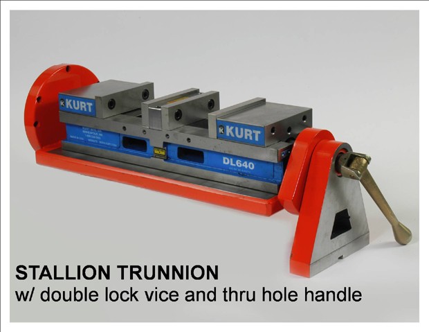
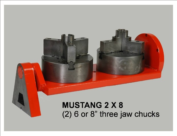
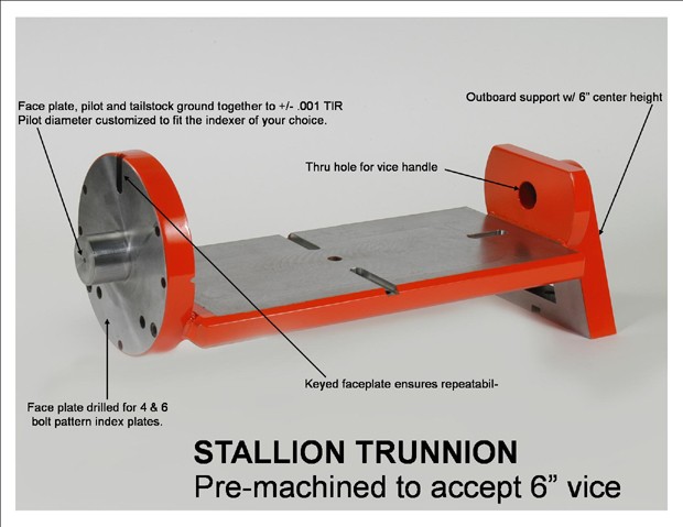
In terms of scale, I want to be able to use tooling like this:
Links
Some other's 4th axis projects:
Nice one made by Bob Adams from tapered roller bearings.
Very cool servo driven 4th axis with disk brake.
|
Do you want to be a better CNC'er in 37 Seconds? Get Better Tool Life, Surface Finish, and Material Removal Rates Fast. It's that easy. You can install and get results now.
|
||||||||||||||||||
| ||||||||||||||||||