Introduction to Datums
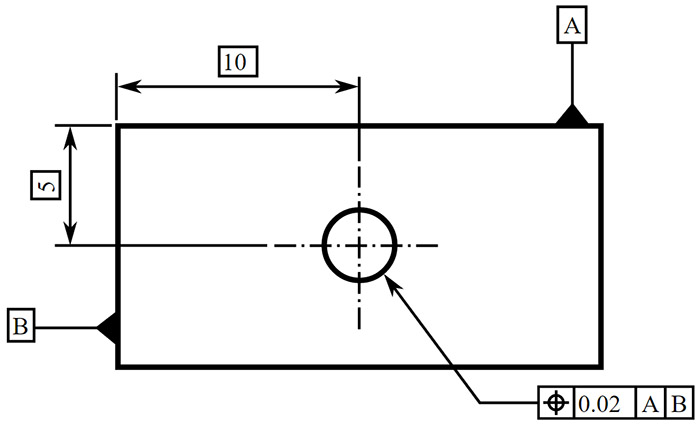
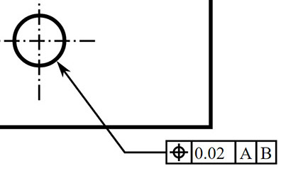
Datums tell us where to measure from. Calling them out clearly and labelling each Feature Control Block with the applicable Datums makes it completely clear how things are to be measured. In the drwaing below, A and B are the Datums used to establish the center of the hole using the Position Symbol and the Feature Control Block for the hole center..

A simple drawing with GD&T symbols. Image Source
GD&T positions every part within a Datum Reference Frame (DRF). Some say the DRF is the most important concept in geometric positioning and tolerancing because it provides the skeleton or frame of reference to which all requirements are connected. For that reason, we want to start early with a solid grounding on Datums and Datum Reference Frames.
Definition of a Datum
A Datum is a plane, axis, or point location that GD&T dimensional tolerances are referenced to. Typically, multiple features will be referenced by each datum, so they're a very important part of the whole thing. Nearly every GD&T symbol except for form tolerances (straightness, flatness, circularity, and cylindricity) can use datums to help specify the geometric control that is needed on the part.
How Datums Are Shown On Drawings
As we said in the definition, Datums are planes, axes, or point locations, and that's exactly how they show up on a drawing. Let's go through each one to see how it looks:
On a Surface (Plane)

Two examples of Datums on a Surface
We can place the datum symbol either on the surface or on one extension line from the surface. For any surface other than a round cylinder, the datum is strictly on the side where the symbol is shown. However, for a round cylinder, the datum is the entire round surface.
On an Axis
Place the symbol on the dimension of a diametric tolerance for Axis control:

A Datum on an Axis
Remember: this places the Datum on the central axis through the feature, not the surface of the feature. Placing the Datum on an axis is common with GD&T symbols that can have axis control like runout, perpendicularity, or concentricity.
On a Point or Hole's Axis
To establish a datum axis on a feature such as a hole, there are a number of ways to place the symbol for the datum:

The "A" Datum can appear in these three different places on a drawing...
Referring to the example above, the "A" Datum can appear in these three different places on a drawing:
- It can be placed directly on the hole, as in the leftmost case. It is of course referring to the axis and not the surface of the hole.
- It can be placed on the leader pointing to the hole as it is in the middle case.
- It can be placed on the Feature Control Frame for the hole.
In addition, it could be shown on a side view by denoting the axis.
Datums vs Datum Features and Datum Targets
At this point it is important to talk about the difference between a Datum and a Datum Feature--they are not the same though it is tempting to refer to them as such at first. Datums are abstract geometrical concepts. They correspond to points, lines, and planes. When we refer to the tangible feature on the part that the Datum is associated with, we call it a Datum Feature. The reason they're not the same is perhaps small, but significant. It is because real features are never perfect abstract geometrical concepts. Surfaces on parts are not perfectly flat planes. Edges on parts are wavy and are not perfect lines.
The standard itself defines a Datum Feature as, "An actual feature of a part that is used to establish a datum."
You may also come across the term Datum Target, which is defined as, "A specified point, line, or area on a part used to establish a datum."
Definition of a Datum Reference Frame
This one starts out simple:
A Datum Reference Frame is a coordinate system, and preferably it is a Cartesian coordinate system.
Coordinate systems are valuable because they're used to locate objects. In GD&T they are used to orient and locate tolerance zones.
Datum Reference Frames and 6 Degrees of Freedom
Every Datum exists within the context of some Datum Reference Frame. In practice, we must eliminate 6 degrees of freedom before we can fully locate and orient a part within a Datum Reference Frame:

Controlling 6 degrees of freedom...
Controlling 6 degrees of freedom means controlling 3 linear distances from Datum planes to establish an X, Y, and Z position and controlling 3 rotary positions to orient the part at that position. We refer to the translational degrees of freedom as X, Y, and Z and the rotational degrees as u, v, and w.
The 3-2-1 Rule and Points of Contact
The 3-2-1 rule defines the minimum number of points of contact required for a part datum feature with its primary, secondary, and tertiary datum planes. It only applies when all three plaines are used. The 3-2-1 rule says:
- The primary datum feature has at least 3 points of contact with its datum plane.
- The secondary datum feature has at least 2 points of contact with its datum plane.
- The tertiary datum feature has at least one point of contact with its datum plane.
The 3-2-1 rule only applies to planer datum features.
Inclined Datum Features
One may specify a datum feature that is at an angle other than 90 degrees relative to other datum features. These are called Inclined Datum Features.

Datum C corresponds to an Inclined Datum Feature...
Datums in the Feature Control Frame and Order of Precedence
Datums are specified in the Feature Control Frame in an Order of Precedence. This Feature Control Frame has 2 Datums specified (A and B):

A Feature Control Frame...
Datum A is the Primary Datum and B is the Secondary Datum. If there had been a third Datum, it would be called the "Tertiary Datum." It is not necessary to specify the Datums in alphabetical order.
The first step in dimensioning a part is always to select the Datums. When selecting Datums, designers should consider the following characteristics:
- Functional surfaces
- Mating surfaces
- Readily accessible surfaces
- Surfaces of sufficient sizes to allow repeatable measurements
Datums are important and care must be taken when selecting them. They must be easily identifiable on the part. When parts are symmetrical or have identical features that make identification of Datum Features difficult, the Datum Features should be physically identified.
Conclusion
By now you have an idea of how Datums are shown on drawings and how they're used to establish a coordinate system. You can read them, at least a little bit, but I'll bet they still don't feel obvious and you're wondering how to "write" them (in other words, how to choose Datum Features on your parts).
We'll have more on exactly how to choose Datum Features shortly. First, we need to talk about Datum Feature Simulators.
Next Article: Datum Feature Simulators
|
Do you want to be a better CNC'er in 37 Seconds? Get Better Tool Life, Surface Finish, and Material Removal Rates Fast. It's that easy. You can install and get results in a matter of minutes.
|
||||||||||||||||||
| ||||||||||||||||||