GD&T Tutorial Home GD&T Symbols
CNCCookbook Beginner's Guide to GD&T: Straightness
GD&T Straightness Symbol
Definition of Straightness and Drawing Callouts
In GD&T, Straightness can be used for two very different functions--Surface Straightness and Axis Straightness.
Surface Straightness
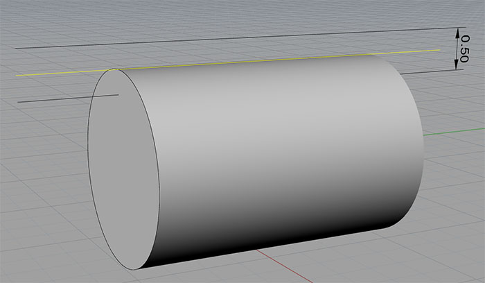
Surface Straightness is a tolerance that controls a line somewhere on a surface or a feature. For example, suppose we are controlling Surface Straightness on a cylindrical part or feature of a part. Pictorially, here's what that means:

Surface Straightness is the maximum deviation from the yellow line on the cylindrical surface...

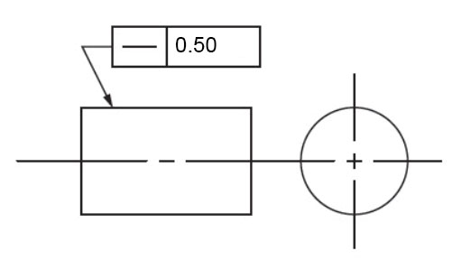
Surface Straightness callout for the drawing above...
The Surface Straightness callout points the arrow to the surface and gives the tolerance.
Axis Straightness
Axis Straightness is the tolerance that controls how much curve is allowed in a part's axis.
Imagine the same sort of drawing as what we have above, only the line is on the axis rather than the surface. Now we are controlling the Axis Straightness. We specify how much it may vary from the ideal, just as with Surface Straightness. One other difference is that the axis may vary in more than one dimension, so the tolerance zone must be cylindrical around the line, rather than just being above and below the line.
When using Axis Straightness, MMC is often called out.
Gaging and Measurement of Straightness
Surface Straightness is pretty easy to gage--we can simply sweep an indicator along the Straightness line called out and measure the deviation in that way.
Axis Straightness is typically measured with a cylindrical gage made just enough larger than the diameter of the feature to accomadate the variation that's allowed. By using an MMC callout, we can ensure that both by virtue of straightness and dimensionally, the part will always fit in a given size hole. Therefore, if you make a part smaller in OD, you gain bonus tolerance which allows the part to be correspondingly less straight.
Usage Notes
In some sense, Surface Straightness is a 2-dimensional version of Flatness. Both are measured without datums and both are used to control and refine the size of a feature. In the same sort of way, we can consider Axis Straightness to be related to Axis Parallelism and Perpendicularity since these are all concerned with controlling a center axis within a cylindrical tolerance zone.
Surface Straightness is very commonly used for surfaces that have to mate with another part while providing a seal. Axis Straightness, OTOH, is most commonly used when designing pins that must fit in some specified bore.
|
Do you want to be a better CNC'er in 37 Seconds? Get Better Tool Life, Surface Finish, and Material Removal Rates Fast. It's that easy. You can install and get results in a matter of minutes.
|
||||||||||||||||||
| ||||||||||||||||||