CNCCookbook: Be a Better CNC'er

THREE WAYS TO SHARE

Beginner's Guide to
Simulating and Verifying CNC Parts

Deliverable: Desk Checked G-Code Program and Setup Sheet

G-Code Simulator

A G-Code Simulator like G-Wizard Editor can save valuable time and trouble...

G-Code simulation can save us valuable time and trouble. Ideally, we won't need to proof programs on the machine, but reaching that level requires considerable experience, discipline, and powerful software tools. For most, simulation is a way to find many, but not all problems and a Program Proofing step will still be required.

Why is Simulation optional?

We can determine if the G-Code Program can be safely run entirely by "cutting air" at the machine, and that's what many CNC'ers do. That's why we say Simulation is "optional."

However, the more that can be discovered with a software simulator, the easier Proofing the program will be, and the less time we'll waste at the machine. For production shops, keeping the spindles turning as much as possible means more profits, so Simulation can save money.

For most any CNC'er, Simulation will save time and frustration because it's faster and easier to run simulation software and fix any problems while you're sitting right at your CADCAM workstation than to deal with it at the machine and potentially have to go back and forth.

Our customers recently helped us quantify the benefits, and we were surprised at how much value they were getting from Toolpath Simulation.  It’s no wonder it’s become a must have tool in the shop. In fact, the adoption rate is surprisingly large across the industry.

By the way--all software has bugs, especially complex software like CADCAM. For a real world example, see our recent article:

What Every CNC'er Needs to Fix CAM Glitches Quickly and Easily


1

Deliverable: G-Code for the Part + Setup Sheet

The Backplot is a graphical 3D display of tool motions...

The Backplot is a graphical 3D display of the tool motions your g-code program will command the CNC Machine to make. You can tell a lot from a quick check of a backplot. For example, any surprising moves well outside the normal envelope of the motions are probably a bad idea. The tool motions should roughly correspond to the shape of your part.

You can run the backplot in the simulator and see the tool motions as they will unfold when the g-code is run. Watching this animation can also reveal issues that are unexpected. For example, you might find operations are happening in a different order than you expect or desire.


2

Check for Collisions and Gouges

Deliverable: Program checked for Collisions and Gouges
Vericut simulation software showing a gouge in red on the simulated part...

Higher-end Simulation Software has Collision and Gouge checking.

With Collision checking, your machine and the workholding, such as a milling vise, will be pictured in the simulation. The simulator will automatically detect whether the tool comes into contact with the machine or workholding, both of which are generally very bad and should be avoided.

Gouging is when the tool touches the part while moving at rapids speeds. This can happen if the tool wasn't retracted far enough before rapids were commanded. In most cases, this will be way to fast and the tool can be broken or chipped. These are again, things to be avoided.

Collision detection can be in the form of Soft Limits on your axis motion. This is less powerful than checking against real 3D models of your machine and workholding, but can still be very valuable. For example, you might know that your 4th axis is at a particular Y-coordinate and you want to avoid any tool motion on the wrong side of that coordinate lest the tool collide with an expensive 4th axis.

Note that while this checking makes collisions and gouges less likely, they're still possible. For example, entering different tool length offsets on the machine than were assumed in the simulator could result in collisions that the simulator didn't detect.

Resources:

- Using G-Wizard Editor's Soft Limit Alarms to Spot Crashes Before They Happen.


3

Deliverable: Program checked for Machine Alarms and Other Errors

Spindle alarm on a Fanuc controller...

Many times more subtle errors can cause a part program to alarm out on the machine. For example, most machines will send an alarm and stop the part program if they encounter an arc command where the distance from each endpoint to the center of the arc differs by too much. The alarm is sent because it's clear that there must've been a mistake of some kind made.

A good simulator can check for all sorts of Machine Alarm Errors so you aren't scratching your head wondering what's gone wrong in the middle of running the program on a machine.

Some error checking is more along the lines of a sanity check. For example, a simulator might check whether a tool was selected and spindle rpms and feedrate were selected before feed motion occurs.


4

Check Tool List

Deliverable: Setup Sheet Tool List confirmed to match Part Program

Tool Crib display in G-Wizard Editor...

A good simulator will generate a list of the tools used by the g-code program. This list should be compared to the list in your Setup Sheet to make sure that they agree. Make sure all the same tools used by the program are in the Setup Sheet and that they have the same tool numbers so the right tools are selected from the Tool Changer.


5

Check Overall Program Stats

Deliverable: Overall Program Stats checked against expectations for the program.

Simulators often have stat sheets that show the overall statistics for a part program. Such statistics include:

- Extent of travels in each axis

- Running time for the program

- etc..

Making a quick read of the statistics to be sure they're in line with expectations is always a good idea.

The stat sheet at right is from our G-Wizard Editor Software.

G Code Program Statistics
6

Check Tolerances vs Original CAD Model

Deliverable: Machining operations verified to be within tolerances described by the CAD Model.

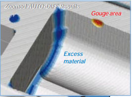
Vericut simulation software showing excess material that should've been removed according to the CAD model on the simulated part...

Higher-end Simulation Software has the ability to accept a CAD model of a part and compare it to a simulated model to see where the two differ. In the simulated model, simulated cutters carve away material as commanded by the part program.

This is a great final check that will identify cases where the part looked good visually in the simulation, but was actually off by more than some specified tolerance from the CAD model.


Back to How to Make CNC Parts

 
All material © 2010-2016, CNCCookbook, Inc.