|
|
|
|
|
|
|
Do you want to be a better CNC'er in 37 Seconds? Get Better Tool Life, Surface Finish, and Material Removal Rates Fast. It's that easy. You can install and get results now. |
 |
Dealing With Chatter When Turning or Milling CNC Feeds and Speeds Cookbook |
I Need to Solve a Chatter Problem Right Now!
If you found this page because you have a problem with chatter right now and not because you're reading through our Cookbook or are just curious to learn, scroll down the page. We'll tell you what to do!
What is Chatter?
Chatter is a resonant phenomenon where the machine or workpiece vibrate. It can become quite violent and generate a distinctive loud noise. It's almost never a good idea to keep machine in the face of strong chatter--chatter is very bad for your tool life, interferes with the accuracy of the machining operation, and will shorten the life of your machine too. On the other hand, many jobs run just fine with a little touch of chatter here or there. We've all seen milling jobs that have a little chatter at certain points in the toolpath--often you'll hear a little squeak as the cutter makes its way through a corner, for example.
Chatter can feed on itself, much like the feedback on a loudspeaker PA system that creates those terrible screeching noises. For that reason, it is sometimes called "regenerative chatter." The regenerative phenomenon is key to understanding how chatter works.
Now imagine what happens if you make a second pass over a surface that is already wavy from chatter--the forces on your cutter vary with the peaks and troughs of the waves. This is the feedback phenomenon which intensifies chatter by making more waves of the same frequency on your workpiece.
Two Kinds of Chatter: Tool Chatter and Workpiece Chatter
There are two kinds of chatter to be aware of--tool chatter and workpiece chatter. With Tool Chatter, your machine and tool are doing the vibrating, which is then transmitted to the workpiece. With Workpiece Chatter, the wall of the workpiece is vibrating. The latter usually only happens when dealing with thin walls, but it can be just as much or more of a problem than Tool Chatter. We'll be focusing on Tool Chatter for this article, but you can try these same techniques to reduce Workpiece Chatter. Before we move on, there are two good tips for Workpiece Chatter.
First, maximize the beef in the workpiece through toolpaths that don't strip away too much material too soon. We'll have more detail on that on the Long Reach and Thin Wall article. Second, you may have to change the frequency of the workpiece through various measures. One way to increase its rigidity is to support the walls with a filling material that's easy to remove when you're done machining. Wax, low melting point tooling materials (both special plastics and metal alloys are available for this purpose), and even the strategy of filling the void with a mixture of vaseline and lead shot have been suggested. For the latter, melt the vaseline over low heat, add the lead shot, pour it in, and let cool.
Minimizing Chatter by Reducing Tool Deflection
Let's say you're not trying to eek out the maximum material removal rate to shave some pennies off a job. How can you avoid even getting started with chatter?
Imagine that your spindle is pumping horsepower into the tool, and in the process of making chips, that horsepower creates forces that act on the tool and the workpiece. With enough force, the tool deflects. Remember, chatter is a resonance phenomenon. Imagine applying force to one tine of a tuning fork, thus deflecting it. If you release that force, the tine vibrates at its resonant frequency. Same thing with your tool. When the flute on the cutter hits air, the force on that "tine" is released.
Now let's say you minimized the deflection on the tine. Below some critical value, you'd hardly hear it vibrate at all. That's the point of controlling tool deflection. The big tooling manufacturer's tell us that chatter can start to cause problems when tool deflection exceeds 0.001". That's not to say you won't have a few problems with deflection short of that, but the more you exceed 0.001", the more chatter becomes a certainty.
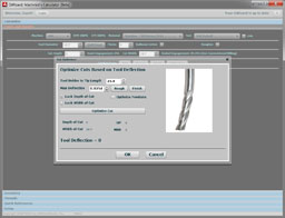
Using our G-Wizard software's Cut Optimizer, you can optimize your cut width or depth of cut to keep deflection below that critical 0.001" value.
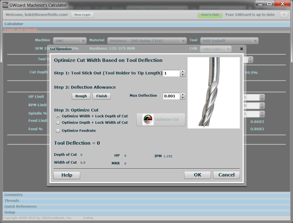
G-Wizard's Cut Optimizer minimizes tool deflection, which will cut chatter way down...
If you're curious, sign up for our free 30-day trial right now and give G-Wizard a try.
Minimizing Chatter via Spindle Speed and Other Tricks
Most machinist's first reaction to chatter is to slow down (which reduces deflection and hence chatter as well as changing the spindle frequency), followed by looking for ways of increasing rigidity. Nothing wrong with increasing rigidity, but if you're an experienced machinist and you know you have a good setup, there are better approaches than just slowing down to minimize chatter.
Since chatter is a resonant phenomenon that is excited by the tool flutes striking the workpiece, it only makes sense that certain spindle speeds will beat on the workpiece at exactly the right frequency to maximize chatter. It's like that old trick where you rub your moistened finger around the rim of a wine glass until it starts to hum.
In order to minimize chatter, we need to find out which frequencies to avoid, or we can reverse that problem and look for frequencies where we can push hard without exciting chatter. This is why slowing down may work, but speeding up may work just as well or even better. When chatter hits, play with your spindle RPM's a bit to see whether you can make it stop. Try increasing the speed first, and then try slowing down. It may be that just twisting the knob solves your problem.
Assuming a little knob twisting won't work and you have maximized rigidity, look for other things that change the frequency:
- Change the number of flutes on your cutter. This changes the frequency quite a lot. Unless you're running a 2 flute, you can always go to one or more fewer flutes. Actually, you can even by single flute cutters which I've heard of machinists taking advantage of for really bad chatter circumstances on a part they make frequently. With indexable tooling, try removing an insert or two, assuming you have multiples to spare. Remember to recalculate your feeds and speeds if you start monkeying with flutes!
- Fiddle with tool stickout. This is a practice called "Tool Tuning". Changing stickout as little as 0.100" can change the chatter frequency. As well as trying shorter stickout (which increases rigidity), don't be afraid to try longer stickout. Even though it will reduce rigidity, it will change the chatter frequency, hopefully to some place where it isn't bothering your job. Be sure to recheck your tool deflection if you change stickout. And speaking of tool deflection, you can reduce the deflection and that will minimize the chances of exciting chatter. A good guideline when roughing is to keep it below 0.001". As you go above that number, chatter and tool breakage are more and more likely.
Chatter and Tool Nose Radius when Turning
If you experience chatter in the corners, try reducing Tool Nose Radius. A smaller TNR will reduce cutting pressures. Always use a TNR smaller than the radius you're cutting.
What Happens if We Make Chatter a Science?
What do you do when twisting the RPM knob, increasing rigidity, and the other tricks don't solve the problem? What if you want to really push your Material Removal Rates as high as possible, or you need to remove every last vibration you can for surface finish? This is when you need to make Chatter a Science and get serious about understanding how to get rid of it.
It turns out that we can make a pictorial representation of the likelihood of chatter for a certain combination of machine, tooling, spindle rpm, and so forth. This representation is called a "Stability Lobe Diagram". Here is a schematic representation of a Stability Lobe Diagram showing regions where chatter occurs:
Think of the chip width as a measure of how hard we can push the machine at a given spindle speed. Note how narrow the stable zones are. This diagram is telling you that the machinist that understands their machine's stable zones has found the profitable high performance "sweet spots" for machining. The official term for a sweet spot is that it is a "Stable Milling Speed." Imagine the poor machinist that fires up their machine at a set of feeds and speeds that correspond to one of the troughs, but is still in the unstable zone. That poor machinist is having to run many times slower than his competitor who has made chatter a science and he probably doesn't even understand why. You better believe the big successful machining operations have figured this stuff out and built it into their daily productivity. For everyone else, it is the luck of the draw whether your particular combination hits a peak or a valley based on the feeds and speeds you've chosen.
Consider that "faster" isn't always, well, faster. Take that last trough. Suppose our feeds and speeds calculator tells us to run at a spindle speed right in that trough. We've bought the ultimate killer solid green unobtanium coated endmills, we stuck them in our bad-mamma-jamma model 2000XL 26-axis machining center, and we turned the loud knobs all the way up to 11. We are gonna make us some big time chips now, right?
Nope.
You're gonna be in that unhappy chatter trough taking light cuts and cursing all the way. But, if you knew where that peak was just to the left or right of the trough, man you could kick it up about 5 or 6 notches and then you'd be making some chips.
Chatter Myths
Chatter is a complex phenomenon, so there are many myths about how to combat it. Unfortunately, the myths don't hold up to the actual physics of what's going on. If you follow the myths, you may accidentally cause something to change that affects the chatter, or you may not. Either way, it isn't the most efficient way to combat chatter by a long shot, so let's identify the myths so you can quit wasting time on them.
Myth #1 - Chatter is caused by unbalance, such as toolholder unbalance
The difference is that toolholder unbalance is forced unbalance, while chatter is self-excited by the regenerative process described above.
How can you tell the difference?
The two occur at different frequencies. In practice, it's not so easy to tell which is which, however. But, you can balance various components and discover you still have chatter.
Myth #2 - Chatter is caused by a lack of chipload
You'll often hear "experienced machinists" encourage you to load up the tool. Inadequate chatter leads to chipload they'll say.
Inadequate chipload has little or nothing to do with chatter. You can change the rpms while maintaining the identical chipload and the chatter will most likely go away if the rpm is sufficiently different.
Now that you know what a stability lobe diagram is, you can understand why chipload is not the major issue. Chipload affects cutting force, and as the diagram shows, with enough cutting force, we can get chatter at any spindle rpm.
Reducing chipload will almost always reduce cutting force, which is why it makes little sense that too little chipload induces chatter.
There are two possible exceptions if you're at a very vulnerable rpm on the stability lobe diagram:
1. Reducing chipload is causing rubbing, which can considerably increase chipload.
2. Reducing chipload is causing the cutter not to get below the work hardened zone on materials that work harden.
Both increase cutting force, but the real problem is we were attempting to cut at an rpm that was vulnerable to chatter at very low cutting forces anyway. We compounded that with improper chipload, which only made matters worse.
Use proper chiploads, but you will also need to select rpm ranges that don't favor chatter (or make the other changes we discuss).
Myth #3 - Chatter is caused by the setup or feeds and speeds, not the machine or tooling
Not true. This is just another variation on the apply heavier chiploads formula. In this version the experienced machinists want us to lower the sfm and crank up the chiploads.
This technique is called process dampening, and according to Moldmaking Technology, it can work but is far from optimum:
Applying heavier chip loads would not be the best thing to try to eliminate chatter; rpm should be the first thing examined. Lowering sfm is not a good way to maximize the operation. This is a tactic that has been used for many years and although it does work, it is undesirable—called process dampening. If you are working on one part it may be useful, but if you are running production it is too costly. Process dampening keeps the cutter in the cut for a longer period of time to keep it from chattering resulting in very low MRR while putting high stress upon the machine tool and cutter assemblies.
Enough myth busting, let's get back to the science of chatter!
Where Can I Get a Stability Lobe Diagram for My Machine?
Okay, now where the heck do you get your Stability Lobe Diagram? Your BMJ Model 2000XL VMC didn't come with one. There's not one in tooling catalog either. What now?
Well, there are two paths to getting together a Stability Lobe Diagram--you can map one out by hand or you can invest in a service or equipment that can measure it analytically. There are various companies in the analytical business, and they usually follow one of two approaches. In one approach, you load your tool in the machine and they strike it with a special instrumented mallet. The instrumentation measures the frequency of the "ringing" and out pops your diagram. Cool beans! The second approach involves the ability to listen to the chatter as it is happening and produce an analysis.
Both of these methods will work, but the equipment and services are not particularly cheap. Chalk up one more advantage for a big operation over the little guy. They can buy that stuff and amortize over a lot of jobs.
There's still hope though, because it isn't that hard to get it together and map out your chatter by hand for a small shop or even a home shop machinist. Before we get into that, we need to talk a bit about the repeatability of chatter.
The Repeatability of Chatter: You Can Map Out Chatter Zones
Chatter is not some random thing that is unpredictable, it is actually reasonably well behaved. We're not very good at predicting it purely using math and no empirical data, but the number of variables involved is small, and you should be aware of them. Here is a list of conditions that if you repeat them, you'll get pretty close to the same chatter every time:
Chatter Repeatability Factors |
|
Machine |
Each machine will have its own distinctive chatter frequencies. Even machines from the same maker with consecutive serial numbers can differ enough that you shouldn't assume they are the same. |
Toolholder Make and Model |
The toolholder matters, but it doesn't literally have to be the same toolholder. Chatter frequencies are only good for one type, brand, and assembly style of toolholder. So, if you have a Parlec ER32 chuck and a MariTool, that's two different frequencies. But if you have all MariTool ER32 collet chucks, unless they have physical differences (different reach or other obvious dimensional difference), they should all behave the same. Ideally, you are torquing the collet nut to the same torque, etc., but it shouldn't be too far out even if you're not using a torque wrench on your collet chucks. |
Cutter Make and Model |
Cutters are just like the toolholders. Select the same make and model, but it doesn't literally have to be the same cutter. |
Stickout |
This is very important. If you change the stickout at all, the freqs will change. A lot of shops just stick the cutter in the holder and go on down the road. It is worth standardizing your stickouts so you can repeat them. A change of 0.100" is enough to change the frequencies. As mentioned above, sometimes you can use this to your advantage through "tool tuning". Don't be afraid to try both shorter and longer stickout. Even though longer is less rigid, the goal is to move the frequency away from where your spindle rpm needs to be for best material removal. If you find that stickout + cutter + toolholder combo for a machine, write it down. That information is money in your bank account. |
Just four variables need to be controlled to make chatter reproducible: Machine, Toolholder, Cutter, and Stickout. That's not so bad, is it?
There is a little bit of bad news: each combination of those variables is a different stability lobe configuration.
"Whoa!", you say. How the heck am I going to deal with all those combinations?
The answer is that you'll be dealing with them over time, and for those few combinations that you use often enough that it matters for your shop. Start out with the tooling you most commonly use for roughing. That's where the hogging really matters. If you have to slow down a finish pass or some tooling combination that you only use very seldom, put that on hold or ignore it entirely.
By now, you're wondering:
- What about workholding?
- What about material?
- What about the specific toolpath or nature of the part?
The good news is that regenerative chatter is at its worst when the machine and tool are doing the vibrating. Yes, workpiece chatter is a problem to as we have discussed, but you care about the machine chatter first. In those cases, you don't have to worry so much about the workholding, material, or the other specifics. These four variables control repeatability. Use the same 4 choices for the variables, and your chatter frequencies will be the same. Make a cut that chattered at some point with those variables, and if you apply enough force through enough feedrate, you'll get chatter again. Likewise, if you avoided chatter, then up to the amount of force you were good to will be good again. And if you were lucky enough to be in a chatter sweet spot (stable zone) on the lobe diagram, you might even be able to run a lot more force.
Using G-Wizard's Chatter Pitch Calculator for Stable Milling Speeds
Let's put all that Chatter Mapping and Stability Lobe Diagram stuff on hold for a minute. You have a chatter problem right now and you don't have time to go doing a lot of research. You're in luck, because our G-Wizard CNC Calculator has a Chatter Calculator that can help out. Let's go through a typical example of its use:
You just ran a cut on a job and the whole shop was holding their ears from all the squealing. You need to know three things:
1. Your surface speed.
2. The number of flutes on the cutter.
3. The chatter pitch, which is the separation, peak to peak, of the "wave marks" or chatter marks on the workpiece.
Let's say you had 200 SFM surface speed, a 4 flute cutter, and 0.005" separation of marks. Here is what G-Wizard's Chatter Calculator would show:
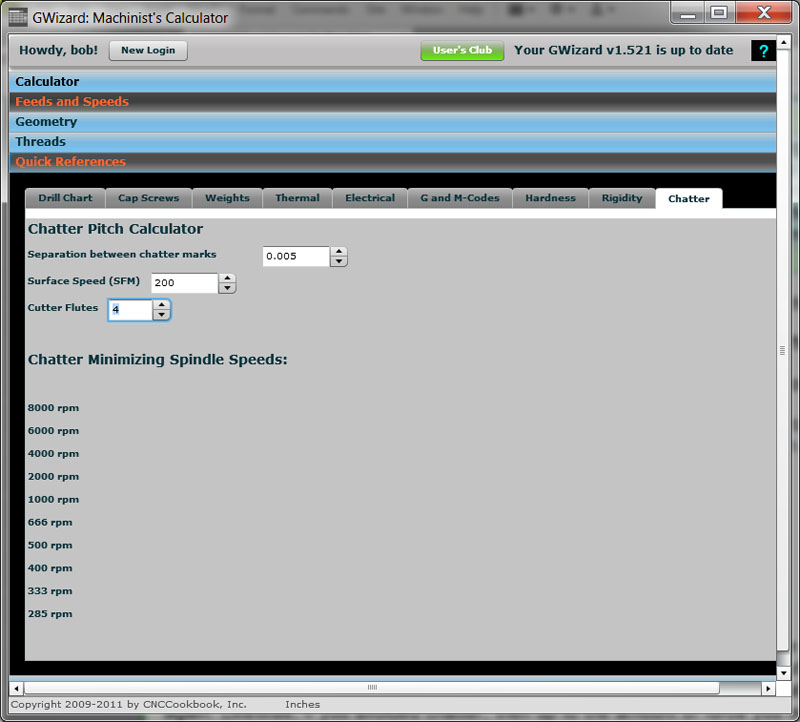
G-Wizard Chatter Calculator...
Note the table labeled "Chatter Minimizing Spindle Speeds". Those are the rpms that minimize the chatter frequency that caused the chatter you just experienced. In other words, those numbers represent the spindle rpm that is least likely to excite the chatter. Those speeds will actually interfere with the chatter and break it up to minimize it. They're the tips of the peaks on the stability lobe diagram. The chatter experts call them Stable Milling Speeds.
Pick the one that is closest to the speed G-Wizard recommends on the feeds and speeds calculator. You'll have to make a determination if the best one is faster than GW's recommended rpm--if it isn't too far above and you have confidence in your tooling, go for it. Remember that the higher rpms can reduce tool life if you get going too fast.
That's all there is to it!
If you've never played with G-Wizard, sign up for our free 30-day trial right now: you'll be glad you did.
Tips for Measuring the Chatter Pitch
It tends to be harder than it looks. In the worst case, you can try to use a digital calipers. That's not very accurate, and the marks can be hard to see. The best tool for the job is an optical comparator or some other optical device that is well lit and can overlay a measurement reticle on the marks. I find that if you have a digital camera that can take close up shots with decent magnification, you can get pretty good results from that.
Programs like Photoshop have the ability to measure features on images. You'll need to have some reference in the photo. If you've got chatter along an edge, the reference can be the total thickness of the edge. Try to take the photo look dead onto the chatter--angles will distort your ability to measure accurately.
Creating a Chatter Map via Cutting Knowledge Base
Any time you find a combination that chatters, your first reaction is to be unhappy. It interrupts your work and it is a problem to deal with. Try thinking about it another way--when you get a combination that chatters, you have found something valuable. You've plotted a point on your stability lobe diagram. If you're able to run the G-Wizard Chatter Calculator, you even have a list of spindle speeds that will minimize chatter for that combination.
The trick with all that is getting organized and having the information at your fingertips when you need it. If it's written on the back of a greasy napkin that used to sit in a particular corner of the shop or your desk, chances are you'll be starting over from scratch and you'll soon be cursing chatter again. What you need is some kind of organized database for the information. The machining world has such a thing--it's called a "Knowledge Base" and is part of the discipline of "Knowledge Based Machining." Some high end CAM packages like Esprit have it and some shops have built their own Knowledge Bases using everything from pencil and paper to simple databases like Microsoft Access.
At CNCCookbook, we've built an easy-to-use Cutting KB (KB is short for "Knowledge Base") into our G-Wizard Feeds and Speeds Calculator. Using it is pretty simple. Dial up the parameters for a cut, and then press the "Search KB" button. Up will pop a list of similar cuts stored in the Knowledge Base. You'll be able to see if you've already been able to do better than the cut you just dialed up, so you can use the better cut instead. You'll also see whether you've just selected a combination that chattered, delivered a poor surface finish, or was bad for tool life in the past. The Cut KB stores your shop's Best Practices that are based on how you operate so that the information will be right for you.
Here's what the Cut KB search screen looks like:
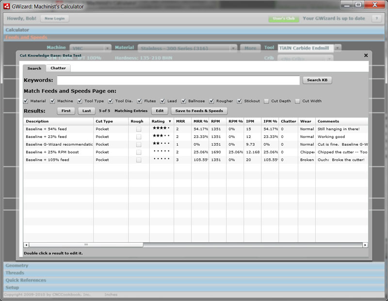
G-Wizard Cut KB Search Results: Right down to a rating system by stars...
Suppose there is nothing in the Cut KB, or you're trying to push the envelope?
No worries. Go back to your parameters in G-Wizard and either punch them up a bit or use them as is. After you make the cut on the machine, remember to go back to G-Wizard and record the result. Just bring up the cutting parameters you used and press "Add to Cut KB". Now the data is recorded for the next time. And remember, it is a good thing when you can add chatter data, broken tool entries, and anything else that helps you find the edge of the envelope.
For more on the Cut KB, check the following links:
Toolroom vs Manufacturing Feeds and Speeds
G-Wizard Cutting KB: Quite a few other links about Knowledge Based Machining on this page too.
Systematically Measuring the Edge of the Envelope
One of the best articles I've seen on this subject was a piece called, "Chatter Control for the Rest of Us," by Peter Zelinski. It's been reprinted in a lot of places and you can even buy it on Amazon, but it started in Modern Machine Shop. Just Google for that title to track it down.
This piece was created by Siemens/UGS, and describes a very simple methodology for mapping out the sort of information you'd want to put into the Cut KB so you know the Stable Milling Speeds for your best combinations. The idea is to create a test for your machine + tooling combo that produces a test piece like this one:
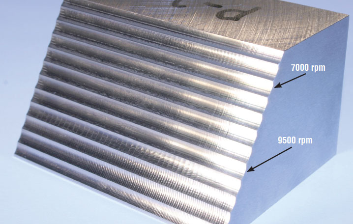
Stable Milling Speed Test for Chatter...
It's readily apparent by inspection that some passes have a lot more chatter than others. From this, you can determine the best speeds. This particular test they called out 7000 rpm and 9500 rpm as Stable Milling Speeds that minimized the chatter. The successive passes for the test were laid out like this:
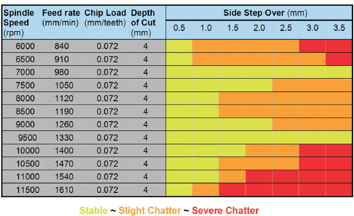
As you can see, they hold chip load and depth of cut constant. The feedrate is based on the rate needed to maintain the desired chipload. Since too much chipload breaks tools quickly, choose one that is at the high end of what you're generally successful with for the exercise. They then proceed to vary the spindle speed and the cutting width (side stepover). The colors indicate how much chatter they encounterd. You get the idea how to do the experiment. In a few hours you can build a pretty good map of a machine and tooling combination for your shop.
At some point, I'll put together g-code to run one of these tests, and we'll also be adding the ability to create and track charts in this format to the G-Wizard Cut KB.
More Anti- Chatter Tips
- Try variable flute angles. You can buy cutters whose flutes are not evenly spaced--this helps reduce the tendency to chatter by breaking up the frequency the flutes can excite. They don't all hit at exact intervals.
- Try a Rougher. For whatever reason, "corncob" roughers seem to be a little less prone to chatter than regular endmills by many accounts. Might be good to keep one handy in your toolbox even if you've moved on to high performance standard endmills and quit using the corncobs.
From time to time we'll be adding any additional tips we come across to this section. Stay tuned!
Next Article: Micromachining
Try the Free Trial Version of G-Wizard Speeds and Feeds Calculator...
![]()
No credit card required--just your name and email.
CNC Milling Feeds and SpeedsContents


|
Do you want to be a better CNC'er in 37 Seconds? Get Better Tool Life, Surface Finish, and Material Removal Rates Fast. It's that easy. You can install and get results now.

|
||||||||||||||||||
| ||||||||||||||||||