|
|
|
|
|
|
|
Do you want to be a better CNC'er in 37 Seconds? Get Better Tool Life, Surface Finish, and Material Removal Rates Fast. It's that easy. You can install and get results now. |
Introduction
Structural Steel is available in a variety of standard sizes. You'll find the dimensions for those sizes in our handy tables below, grouped by structural shape. In addition, there is helpful information on the applicable standards and other basics.
Structural Steel is generally referred to by its profile (for example "I-Beams") and its size. Sizes are determined by standards which are described in the sections for each shape below.
One goal of Structural Steel that goes to determining the shape is that it have high second moments of area, which make them very stiff in respect to their cross-sectional area. This makes them strong relative to the amount of material and weight that must be used in their construction.
![]()
Common Structural Steel Shapes By William Perry of Mercury Business Development - https://commons.wikimedia.org/w/index.php?curid=5326461...
Free Steel Size and Weight Calculator
All the data you're seeking on Standard Steel Sizes is available below in tabular form, but why use tables when a free calculator is available that has all the same information and will also help you calculate weight, volume, and costs for job quoting?
Our G-Wizard Feeds and Speeds Calculator has all that and more built in. When you take our free 30-day trial, you get access to the Free Steel Size and Weight Calculator (and a lot more):
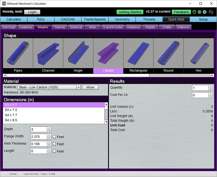
All the standard structural shapes are available in the Free Size and Weight Calculator...
All the standard structural shapes are available in the Free Size and Weight Calculator, and it isn't just for steel--there's a large Material Database with well over a thousand different materials to choose from.
To get your free trial and lifetime access to the Free Size and Weight Calculator, click below:
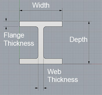
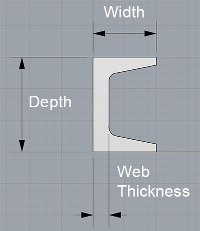
Steel I-Beam Sizes
I-Beams are also known as H-Beams, W-Beams (for "wide flange"), Universal Beams (UB), Rolled Steel Joists (RSJ) or Double-T. I-Beams have an I, or if you rotate it, an H-shaped cross-section. The horizontal elements of the "I" are called "flanges", while the vertical elements are the "web." I-Beams are one of several standard structural shapes for steel, and they are commonly used in construction and civil engineering projects.
The shape of the I-Beam provides versatile strength with a minimum of weight. The web resists shear forces while the flanges resist the bending moment experienced by the beam. Thus I-Beams are very efficient for carrying bending and shear loads in the plane of the web. The weakness of the shape is that it doesn't resist torsional forces nor does it have much capacity in the transverse direction. If strengths in those areas are needed, hollow structural sections (HSS) are preferred.
Steel I-Beams are typically produced by a rolling process that was invented in 1849 by Alphonse Halbou in France. The use of rolled I-Beams was common into the mid-20th century. Today, fabricated I-Beams, which are produced by welding together the flanges and web are also common.
US Standards
In the US, the Wide Flange (W-Beams) are the most common. These beams have flanges which are almost parallel. Relevant standards with yield strengths are:
- ASTM A992: 50,000 - 65,000 psi (340-450 MPa)
- A588: Similar to A572
- A572: 42,000 - 60,000 psi (290 - 410 MPa), but 50,000 psi (340 MPa) is the most common.
- A36: 36,000 psi (250 MPa)
A992 has generally replaced the older A572 and A36 standards.
The American Institute of Steel Construction (AISC) publishes the Steel Construction Manual for designing structures of various shapes. It documents the common approaches, Allowable Stress Design (ASD) and Load and Resistance Factor Design (LRFD), (starting with 13th ed.) to create such designs.
Euronorms
- EN 10024: Hot rolled taper flange I sections
- EN 10034: Structural steel I and H sections
- EN 10162: Cold rolled steel sections
Other Standards
- ASTM A6, American Standard Beams
- IS 808 - Dimensions hot rolled steel beam, column, channel and angle sections
- AS/NZS 3679.1 - Australia and New Zealand standard
Steel I-Beam Sizes (Wide Flange)
Name |
Depth |
Width |
Web Thickness |
Flange Thickness |
Sectional Area |
Weight lbs/ft |
||
| W 27 x 178 | 27.8 | 14.09 | 0.725 | 1.19 | 52.3 | 178 | ||
| W 27 x 161 | 27.6 | 14.02 | 0.66 | 1.08 | 47.4 | 161 | ||
| W 27 x 146 | 27.4 | 14 | 0.605 | 0.975 | 42.9 | 146 | ||
| W 27 x 114 | 27.3 | 10.07 | 0.57 | 0.93 | 33.5 | 114 | ||
| W 27 x 102 | 27.1 | 10.02 | 0.515 | 0.83 | 30 | 102 | ||
| W 27 x 94 | 26.9 | 10 | 0.49 | 0.745 | 27.7 | 94 | ||
| W 27 x 84 | 26.7 | 9.96 | 0.46 | 0.64 | 24.8 | 84 | ||
| W 24 x 162 | 25 | 13 | 0.705 | 1.22 | 47.7 | 162 | ||
| W 24 x 146 | 24.7 | 12.9 | 0.65 | 1.09 | 43 | 146 | ||
| W 24 x 131 | 24.5 | 12.9 | 0.605 | 0.96 | 38.5 | 131 | ||
| W 24 x 117 | 24.3 | 12.8 | 0.55 | 0.85 | 34.4 | 117 | ||
| W 24 x 104 | 24.1 | 12.75 | 0.5 | 0.75 | 30.6 | 104 | ||
| W 24 x 94 | 24.1 | 9.07 | 0.515 | 0.875 | 27.7 | 94 | ||
| W 24 x 84 | 24.1 | 9.02 | 0.47 | 0.77 | 24.7 | 84 | ||
| W 24 x 76 | 23.9 | 9 | 0.44 | 0.68 | 22.4 | 76 | ||
| W 24 x 68 | 23.7 | 8.97 | 0.415 | 0.585 | 20.1 | 68 | ||
| W 24 x 62 | 23.7 | 7.04 | 0.43 | 0.59 | 18.2 | 62 | ||
| W 24 x 55 | 23.6 | 7.01 | 0.395 | 0.505 | 16.2 | 55 | ||
| W 21 x 147 | 22.1 | 12.51 | 0.72 | 1.15 | 43.2 | 147 | ||
| W 21 x 132 | 21.8 | 12.44 | 0.65 | 1.035 | 38.8 | 132 | ||
| W 21 x 122 | 21.7 | 12.39 | 0.6 | 0.96 | 35.9 | 122 | ||
| W 21 x 111 | 21.5 | 12.34 | 0.55 | 0.875 | 32.7 | 111 | ||
| W 21 x 101 | 21.4 | 12.29 | 0.5 | 0.8 | 29.8 | 101 | ||
| W 21 x 93 | 21.6 | 8.42 | 0.58 | 0.93 | 27.3 | 93 | ||
| W 21 x 83 | 21.4 | 8.36 | 0.515 | 835 | 24.3 | 83 | ||
| W 21 x 73 | 21.2 | 8.3 | 0.455 | 0.74 | 21.5 | 73 | ||
| W 21 x 68 | 21.1 | 8.27 | 0.43 | 0.685 | 20 | 68 | ||
| W 21 x 62 | 21 | 8.24 | 0.4 | 0.615 | 18.3 | 62 | ||
| W 21 x 57 | 21.1 | 6.56 | 0.405 | 0.65 | 16.7 | 57 | ||
| W 21 x 50 | 20.8 | 6.53 | 0.38 | 0.535 | 14.7 | 50 | ||
| W 21 x 44 | 20.7 | 6.5 | 0.35 | 0.45 | 13 | 44 | ||
| W 18 x 119 | 19 | 11.27 | 0.655 | 1.06 | 35.1 | 119 | ||
| W 18 x 106 | 18.7 | 11.2 | 0.59 | 0.94 | 31.1 | 106 | ||
| W 18 x 97 | 18.6 | 11.15 | 0.535 | 0.87 | 28.5 | 97 | ||
| W 18 x 86 | 18.4 | 11.09 | 0.48 | 0.77 | 25.3 | 86 | ||
| W 18 x 76 | 18.2 | 11.04 | 0.425 | 0.68 | 22.3 | 76 | ||
| W 18 x 71 | 18.5 | 7.64 | 0.495 | 0.81 | 20.8 | 71 | ||
| W 18 x 65 | 18.4 | 7.59 | 0.45 | 0.75 | 19.1 | 65 | ||
| W 18 x 60 | 18.2 | 7.56 | 0.415 | 0.695 | 17.6 | 60 | ||
| W 18 x 55 | 18.1 | 7.53 | 0.39 | 0.63 | 16.2 | 55 | ||
| W 18 x 50 | 18 | 7.5 | 0.355 | 0.57 | 14.7 | 50 | ||
| W 18 x 46 | 18.1 | 6.06 | 0.36 | 0.605 | 13.5 | 46 | ||
| W 18 x 40 | 17.9 | 6.02 | 0.315 | 0.525 | 11.8 | 40 | ||
| W 18 x 35 | 17.7 | 6 | 0.3 | 0.425 | 10.3 | 35 | ||
| W 16 x 100 | 16.97 | 10.425 | 0.585 | 0.985 | 29.4 | 100 | ||
| W 16 x 89 | 16.75 | 10.365 | 0.525 | 0.875 | 26.2 | 89 | ||
| W 16 x 77 | 16.52 | 10.295 | 0.455 | 0.76 | 22.6 | 77 | ||
| W 16 x 67 | 16.33 | 10.235 | 0.395 | 0.665 | 19.7 | 67 | ||
| W 16 x 57 | 16.43 | 7.12 | 0.43 | 0.715 | 16.8 | 57 | ||
| W 16 x 50 | 16.26 | 7.07 | 0.38 | 0.63 | 14.7 | 50 | ||
| W 16 x 45 | 16.13 | 7.035 | 0.345 | 0.565 | 13.3 | 45 | ||
| W 16 x 40 | 16.01 | 6.995 | 0.305 | 0.505 | 11.8 | 40 | ||
| W 16 x 36 | 15.86 | 6.985 | 0.295 | 0.43 | 10.6 | 36 | ||
| W 16 x 31 | 15.88 | 5.525 | 0.275 | 0.44 | 9.12 | 31 | ||
| W 16 x 26 | 15.69 | 5.5 | 0.25 | 0.345 | 7.68 | 26 | ||
| W 14 x 132 | 14.66 | 14.725 | 0.645 | 1.03 | 38.8 | 132 | ||
| W 14 x 120 | 14.48 | 14.67 | 0.59 | 0.94 | 35.3 | 120 | ||
| W 14 x 109 | 14.32 | 14.605 | 0.525 | 0.86 | 32 | 109 | ||
| W 14 x 99 | 14.16 | 14.565 | 0.485 | 0.78 | 29.1 | 99 | ||
| W 14 x 90 | 14.02 | 14.52 | 0.44 | 0.71 | 26.5 | 90 | ||
| W 14 x 82 | 14.31 | 10.13 | 0.51 | 0.855 | 24.1 | 82 | ||
| W 14 x 74 | 14.17 | 10.07 | 0.45 | 0.785 | 21.8 | 74 | ||
| W 14 x 68 | 14.04 | 10.035 | 0.415 | 0.72 | 20 | 68 | ||
| W 14 x 61 | 13.89 | 9.995 | 0.375 | 0.645 | 17.9 | 61 | ||
| W 14 x 53 | 13.92 | 8.06 | 0.37 | 0.66 | 15.6 | 53 | ||
| W 14 x 48 | 13.79 | 8.03 | 0.34 | 0.595 | 14.1 | 48 | ||
| W 14 x 43 | 13.66 | 7.995 | 0.305 | 0.53 | 12.6 | 43 | ||
| W 14 x 38 | 14.1 | 6.77 | 0.31 | 0.515 | 11.2 | 38 | ||
| W 14 x 34 | 13.98 | 6.745 | 0.285 | 0.455 | 10 | 34 | ||
| W 14 x 30 | 13.84 | 6.73 | 0.27 | 0.385 | 8.85 | 30 | ||
| W 14 x 26 | 13.91 | 5.025 | 0.255 | 0.42 | 7.69 | 26 | ||
| W 14 x 22 | 13.74 | 5 | 0.23 | 0.335 | 6.49 | 22 | ||
| W 12 x 136 | 13.41 | 12.4 | 0.79 | 1.25 | 39.9 | 136 | ||
| W 12 x 120 | 13.12 | 12.32 | 0.71 | 1.105 | 35.3 | 120 | ||
| W 12 x 106 | 12.89 | 12.22 | 0.61 | 0.99 | 31.2 | 106 | ||
| W 12 x 96 | 12.71 | 12.16 | 0.55 | 0.9 | 28.2 | 96 | ||
| W 12 x 87 | 12.53 | 12.125 | 0.515 | 0.81 | 25.6 | 87 | ||
| W 12 x 79 | 12.38 | 12.08 | 0.47 | 0.735 | 23.2 | 79 | ||
| W 12 x 72 | 12.25 | 12.04 | 0.43 | 0.67 | 21.1 | 72 | ||
| W 12 x 65 | 12.12 | 12 | 0.39 | 0.605 | 19.1 | 65 | ||
| W 12 x 58 | 12.19 | 10.01 | 0.36 | 0.64 | 17 | 58 | ||
| W 12 x 53 | 12.06 | 9.995 | 0.345 | 0.575 | 15.6 | 53 | ||
| W 12 x 50 | 12.19 | 8.08 | 0.37 | 0.64 | 14.7 | 50 | ||
| W 12 x 45 | 12.06 | 8.045 | 0.335 | 0.575 | 13.2 | 45 | ||
| W 12 x 40 | 11.94 | 8.005 | 0.295 | 0.515 | 11.8 | 40 | ||
| W 12 x 35 | 12.5 | 6.56 | 0.3 | 0.52 | 10.3 | 35 | ||
| W 12 x 30 | 12.34 | 6.52 | 0.26 | 0.44 | 8.8 | 30 | ||
| W 12 x 26 | 12.22 | 6.49 | 0.23 | 0.38 | 7.7 | 26 | ||
| W 12 x 22 | 12.31 | 4.03 | 0.26 | 0.425 | 6.5 | 22 | ||
| W 12 x 19 | 12.16 | 4.005 | 0.235 | 0.35 | 5.6 | 19 | ||
| W 12 x 16 | 11.99 | 3.99 | 0.22 | 0.265 | 4.7 | 16 | ||
| W 12 x 14 | 11.91 | 3.97 | 0.2 | 0.225 | 4.2 | 14 | ||
| W 10 x 112 | 11.36 | 10.415 | 0.755 | 1.25 | 32.9 | 112 | ||
| W 10 x 100 | 11.1 | 10.34 | 0.68 | 1.112 | 29.4 | 100 | ||
| W 10 x 88 | 10.84 | 10.265 | 0.605 | 0.99 | 25.9 | 88 | ||
| W 10 x 77 | 10.6 | 10.19 | 0.53 | 0.87 | 22.6 | 77 | ||
| W 10 x 68 | 10.4 | 10.13 | 0.47 | 770 | 20 | 68 | ||
| W 10 x 60 | 10.22 | 10.08 | 0.42 | 0.68 | 17.6 | 60 | ||
| W 10 x 54 | 10.09 | 10.03 | 0.37 | 0.615 | 15.8 | 54 | ||
| W 10 x 49 | 9.98 | 10 | 0.34 | 0.56 | 14.4 | 49 | ||
| W 10 x 45 | 10.1 | 8.02 | 0.35 | 0.62 | 13.3 | 45 | ||
| W 10 x 39 | 9.92 | 7.985 | 0.315 | 0.53 | 11.5 | 39 | ||
| W 10 x 33 | 9.73 | 7.96 | 0.29 | 0.435 | 9.71 | 33 | ||
| W 10 x 30 | 10.47 | 5.81 | 0.3 | 0.51 | 8.84 | 30 | ||
| W 10 x 26 | 10.33 | 5.77 | 0.26 | 0.44 | 7.6 | 26 | ||
| W 10 x 22 | 10.17 | 5.75 | 0.24 | 0.36 | 6.5 | 22 | ||
| W 10 x 19 | 10.24 | 4.02 | 0.25 | 0.395 | 5.6 | 19 | ||
| W 10 x 17 | 10.11 | 4.01 | 0.24 | 0.33 | 5 | 17 | ||
| W 10 x 15 | 9.99 | 4 | 0.23 | 0.27 | 4.4 | 15 | ||
| W 10 x 12 | 9.87 | 3.96 | 0.19 | 0.21 | 3.5 | 12 | ||
| W 8 x 67 | 9 | 8.28 | 0.57 | 0.935 | 19.7 | 67 | ||
| W 8 x 58 | 8.75 | 8.22 | 0.51 | 0.81 | 17.1 | 58 | ||
| W 8 x 48 | 8.5 | 8.11 | 0.4 | 0.685 | 14.1 | 48 | ||
| W 8 x 40 | 8.25 | 8.07 | 0.36 | 0.56 | 11.7 | 40 | ||
| W 8 x 35 | 8.12 | 8.02 | 0.31 | 0.495 | 10.3 | 35 | ||
| W 8 x 31 | 8 | 7.995 | 0.285 | 0.435 | 9.1 | 31 | ||
| W 8 x 28 | 8.06 | 6.535 | 0.285 | 0.465 | 8.3 | 28 | ||
| W 8 x 24 | 7.93 | 6.495 | 0.245 | 0.4 | 7.1 | 24 | ||
| W 8 x 21 | 8.28 | 5.27 | 0.25 | 0.4 | 6.2 | 21 | ||
| W 8 x 18 | 8.14 | 5.25 | 0.23 | 0.33 | 5.3 | 18 | ||
| W 8 x 15 | 8.11 | 4.015 | 0.245 | 0.315 | 4.4 | 15 | ||
| W 8 x 13 | 7.99 | 4 | 0.23 | 0.255 | 3.8 | 13 | ||
| W 8 x 10 | 7.89 | 3.94 | 0.17 | 0.205 | 2.9 | 10 | ||
| W 6 x 25 | 6.38 | 6.08 | 0.32 | 0.455 | 7.3 | 25 | ||
| W 6 x 20 | 6.2 | 6.02 | 0.26 | 0.365 | 5.9 | 20 | ||
| W 6 x 16 | 6.28 | 4.03 | 0.26 | 0.405 | 4.7 | 16 | ||
| W 6 x 15 | 5.99 | 5.99 | 0.23 | 0.26 | 4.4 | 15 | ||
| W 6 x 12 | 6.03 | 4 | 0.23 | 0.28 | 3.6 | 12 | ||
| W 6 x 9 | 5.9 | 3.94 | 0.17 | 0.215 | 2.7 | 9 | ||
| W 5 x 19 | 5.15 | 5.03 | 0.27 | 0.43 | 5.5 | 19 | ||
| W 5 x 16 | 5.01 | 5 | 0.24 | 0.36 | 4.7 | 16 | ||
| W 4 x 13 | 4.16 | 4.06 | 0.28 | 0.345 | 3.8 | 13 | ||
Steel I-Beam Sizes (S)
Name |
Depth |
Width |
Web Thickness |
Sectional Area |
Weight lbs/ft |
||
| S 24 x 121 | 24.5 | 8.05 | 0.8 | 35.6 | 121 | ||
| S 24 x 106 | 24.5 | 7.78 | 0.62 | 31.2 | 106 | ||
| S 24 x 100 | 24 | 7.425 | 0.745 | 29.3 | 100 | ||
| S 24 x 90 | 24 | 7.125 | 0.625 | 26.5 | 90 | ||
| S 24 x 80 | 24 | 7 | 0.5 | 23.5 | 80 | ||
| S 20 x 96 | 20.3 | 7.2 | 0.8 | 28.2 | 96 | ||
| S 20 x 86 | 20.3 | 7.06 | 0.66 | 25.3 | 86 | ||
| S 20 x 75 | 20 | 6.385 | 0.635 | 22 | 75 | ||
| S 20 x 66 | 20 | 6.255 | 0.505 | 19.4 | 66 | ||
| S 18 x 70 | 18 | 6.251 | 0.711 | 20.6 | 70 | ||
| S 18 x 54.7 | 18 | 6.001 | 0.461 | 16.1 | 54.7 | ||
| S 15 x 50 | 15 | 5.64 | 0.55 | 14.7 | 50 | ||
| S 15 x 42.9 | 15 | 5.501 | 0.411 | 12.6 | 42.9 | ||
| S 12 x 50 | 12 | 5.477 | 0.687 | 14.7 | 50 | ||
| S 12 x 40.8 | 12 | 5.252 | 0.462 | 12 | 40.8 | ||
| S 12 x 35 | 12 | 5.078 | 0.428 | 10.3 | 35 | ||
| S 12 x 31.8 | 12 | 5 | 0.35 | 9.35 | 31.8 | ||
| S 10 x 35 | 10 | 4.944 | 0.594 | 10.3 | 35 | ||
| S 10 x 25.4 | 10 | 4.661 | 0.311 | 7.46 | 25.4 | ||
| S 8 x 23 | 8 | 4.171 | 0.441 | 6.77 | 23 | ||
| S 8 x 18.4 | 8 | 4.001 | 0.271 | 5.41 | 18.4 | ||
| S 7 x 20 | 7 | 3.86 | 0.45 | 5.88 | 20 | ||
| S 7 x 15.3 | 7 | 3.662 | 0.252 | 4.5 | 15.3 | ||
| S 6 x 17.25 | 6 | 3.565 | 0.465 | 5.07 | 17.25 | ||
| S 6 x 12.5 | 6 | 3.332 | 0.232 | 3.67 | 12.5 | ||
| S 5 x 14.75 | 5 | 3.284 | 0.494 | 4.34 | 14.75 | ||
| S 5 x 10 | 5 | 3.004 | 0.214 | 2.94 | 10 | ||
| S 4 x 9.5 | 4 | 2.796 | 0.326 | 2.79 | 9.5 | ||
| S 4 x 7.7 | 4 | 2.663 | 0.193 | 2.26 | 7.7 | ||
| S 3 x 7.5 | 3 | 2.509 | 0.349 | 2.21 | 7.5 | ||
| S 3 x 5.7 | 3 | 2.33 | 0.17 | 1.67 | 5.7 | ||
Steel Channel Sizes
Structural Channel is also know as C-beam. It's a type of structural steel beam used primarily in building construction and civil engineering. Channel cross section is "C" shaped and consists of a wide web (usually oriented vertically in use) and two "flanges" at the top and bottom of the web.
C-Beams are not symmetrical (at least when used vertically) like I-Beams, which means the bending axis is not centered on the width of the flanges. If we apply a load to the top of a flange, the beam will try to twist away from the web. This may not be a problem for some designs, but it results in channels being less commonly used than I-Beams for structural purposes.
Instead, they are most often used where the large flat web will either be mounted to another flat surface for maximum contact area, or will face outward to hide the flanges for aesthetic reasons.
The applicable US standard for Steel used in Channel is ASTM A-36, which specifies a yield point of 36,000 psi minimum.
Steel Channel Size Chart
Name |
Depth (in) |
Width (in) |
Web Thickness (in) |
Weight Llbs / Foot |
| C 15 x 50 | 15 | 3.716 | 0.716 | 50 |
| C 15 x 40 | 15 | 3.52 | 0.52 | 40 |
| C 15 x 33.9 | 15 | 3.4 | 0.4 | 33.9 |
| C 12 x 30 | 12 | 3.17 | 0.51 | 30 |
| C 12 x 25 | 12 | 3.047 | 0.387 | 25 |
| C 12 x 20.7 | 12 | 2.942 | 0.282 | 20.7 |
| C 10 x 30 | 10 | 3.033 | 0.673 | 30 |
| C 10 x 25 | 10 | 2.886 | 0.526 | 25 |
| C 10 x 20 | 10 | 2.739 | 0.379 | 20 |
| C 10 x 15.3 | 10 | 2.6 | 0.24 | 15.3 |
| C 9 x 20 | 9 | 2.648 | 0.448 | 20 |
| C 9 x 15 | 9 | 2.485 | 0.285 | 15 |
| C 9 x 13.4 | 9 | 2.433 | 0.233 | 13.4 |
| C 8 x 18.75 | 8 | 2.527 | 0.487 | 18.75 |
| C 8 x 13.75 | 8 | 2.343 | 0.303 | 13.75 |
| C 8 x 11.5 | 8 | 2.26 | 0.22 | 11.5 |
| C 7 x 14.75 | 7 | 2.299 | 0.419 | 14.75 |
| C 7 x 12.25 | 7 | 2.194 | 0.314 | 12.25 |
| C 7 x 9.8 | 7 | 2.09 | 0.21 | 9.8 |
| C 6 x 13 | 6 | 2.157 | 0.437 | 13 |
| C 6 x 10.5 | 6 | 2.034 | 0.314 | 10.5 |
| C 6 x 8.2 | 6 | 1.92 | 0.2 | 8.2 |
| C 5 x 9 | 5 | 1.885 | 0.325 | 9 |
| C 5 x 6.7 | 5 | 1.75 | 0.19 | 6.7 |
| C 4 x 7.25 | 4 | 1.721 | 0.321 | 7.25 |
| C 4 x 5.4 | 4 | 1.584 | 0.184 | 5.4 |
| C 3 x 6 | 3 | 1.596 | 0.356 | 6 |
| C 3 x 5 | 3 | 1.498 | 0.258 | 5 |
| C 3 x 4.1 | 3 | 1.41 | 0.17 | 4.1 |
Steel Angle Sizes
Steel Angle is another Structural Steel shape that's commonly available. Angle typically has an L-shaped cross section.
Size |
Depth |
Thickness |
Weight/Ft |
| 12 x 12 | 12 | 1 3/8 | 105 |
| 12 | 1 1/4 | 96.4 | |
| 12 | 1 1/8 | 87.2 | |
| 12 | 1 | 77.8 | |
| 10 x 10 | 10 | 1 3/8 | 87.1 |
| 10 | 1 1/4 | 79.9 | |
| 10 | 1 1/8 | 72.3 | |
| 10 | 1 | 64.7 | |
| 10 | 7/8 | 56.9 | |
| 10 | 3/4 | 49.1 | |
| 8 x 8 | 8 | 1 1/8 | 56.9 |
| 8 | 1 | 51 | |
| 8 | 7/8 | 45 | |
| 8 | 3/4 | 38.9 | |
| 8 | 5/8 | 32.7 | |
| 8 | 9/16 | 29.6 | |
| 8 | 1/2 | 26.4 | |
| 6 x 6 | 6 | 1 | 37.4 |
| 6 | 7/8 | 33.1 | |
| 6 | 3/4 | 28.7 | |
| 6 | 5/8 | 24.2 | |
| 6 | 9/16 | 21.9 | |
| 6 | 1/2 | 19.6 | |
| 6 | 7/16 | 17.2 | |
| 6 | 3/8 | 14.9 | |
| 6 | 5/16 | 12.4 | |
| 5 x 5 | 5 | 7/8 | 27.2 |
| 5 | 3/4 | 23.6 | |
| 5 | 5/8 | 20 | |
| 5 | 1/2 | 16.2 | |
| 5 | 7/16 | 14.3 | |
| 5 | 3/8 | 12.3 | |
| 5 | 5/16 | 10.3 | |
| 4 x 4 | 4 | 3/4 | 18.5 |
| 4 | 5/8 | 15.7 | |
| 4 | 1/2 | 12.8 | |
| 4 | 7/16 | 11.3 | |
| 4 | 3/8 | 9.8 | |
| 4 | 5/16 | 8.2 | |
| 4 | 1/4 | 6.6 | |
| 3 1/2 x 3 1/2 | 3 1/2 | 1/2 | 11.1 |
| 3 1/2 | 7/16 | 9.8 | |
| 3 1/2 | 3/8 | 8.5 | |
| 3 1/2 | 5/16 | 7.2 | |
| 3 1/2 | 1/4 | 5.8 | |
| 3 x 3 | 3 | 1/2 | 9.4 |
| 3 | 7/16 | 8.3 | |
| 3 | 3/8 | 7.2 | |
| 3 | 5/16 | 6.1 | |
| 3 | 1/4 | 4.9 | |
| 3 | 3/16 | 3.7 | |
| 2 1/2 x 2 1/2 | 2 1/2 | 1/2 | 7.7 |
| 2 1/2 | 3/8 | 5.9 | |
| 2 1/2 | 5/16 | 5 | |
| 2 1/2 | 1/4 | 4.1 | |
| 2 1/2 | 3/16 | 3.1 | |
| 2 x 2 | 2 | 3/8 | 4.7 |
| 2 | 5/16 | 3.9 | |
| 2 | 1/4 | 3.2 | |
| 2 | 3/16 | 2.4 | |
| 2 | 1/8 | 1.7 |
Hollow Structural Section (HSS) Sizes
Hollow Structural Sections (HSS) are one of the standard structural steel shapes. HSS sections are profiles with a hollow tubular cross section that is typically square or rectangular, although circular and elliptical setions are also available. These sections are also commonly called tube steel or structural tubing, and they are sometimes mistakenly called "Hollow Structural Steel." Circular sections are sometimes mistakenly called "Steel Pipe" rather than tubing although true steel pipe is dimensioned and classed differently from HSS.
HSS is a term used in the US and other countries that follow US construction and engineering terminology. In the UK, the term HSS is not used. Rather, the basic shapes are referred to as CHS (Circular Hollow Section), SHS (Square Hollow Section), and RHS (Rectangular Hollow Section).
HSS is commonly used in welded steel frames whose members experience loading in multiple directions. Square and circular HSS are very efficient shapes for multi-axis loading because of their uniform geometry along two or more cross-sectional axes. Typically, HSS is available in mild steel such as A500 grade C or grade B.
Hollow Structural Section (HSS) Size Table
Size |
Weight (lb/ft) |
Wall Thickness (in) |
| 32 x 32 x 5/8 | 259.83 | 0.625 |
| 32 x 32 x 1/2 | 210.72 | 0.5 |
| 32 x 32 x 3/8 | 159.37 | 0.375 |
| 30 x 30 x 5/8 | 242.82 | 0.625 |
| 30 x 30 x 1/2 | 197.11 | 0.5 |
| 30 x 30 x 3/8 | 149.16 | 0.375 |
| 28 x 28 x 5/8 | 225.8 | 0.625 |
| 28 x 28 x 1/2 | 183.5 | 0.5 |
| 28 x 28 x 3/8 | 138.95 | 0.375 |
| 26 x 26 x 5/8 | 208.79 | 0.625 |
| 26 x 26 x 1/2 | 169.89 | 0.5 |
| 26 x 26 x 3/8 | 128.74 | 0.375 |
| 24 x 24 x 5/8 | 191.78 | 0.625 |
| 24 x 24 x 1/2 | 156.28 | 0.5 |
| 24 x 24 x 3/8 | 118.53 | 0.375 |
| 22 x 22 x 5/8 | 174.76 | 0.625 |
| 22 x 22 x 1/2 | 142.67 | 0.5 |
| 22 x 22 x 3/8 | 108.32 | 0.375 |
| 20 x 20 x 5/8 | 157.75 | 0.625 |
| 20 x 20 x 1/2 | 129.06 | 0.5 |
| 20 x 20 x 3/8 | 98.12 | 0.375 |
| 18 x 18 x 5/8 | 140.73 | 0.625 |
| 18 x 18 x 1/2 | 115.45 | 0.5 |
| 18 x 18 x 3/8 | 87.91 | 0.375 |
| 16 x 16 x 5/8 | 127.37 | 0.581 |
| 16 x 16 x 1/2 | 103.3 | 0.465 |
| 16 x 16 x 3/8 | 78.52 | 0.349 |
| 16 x 16 x 5/16 | 65.87 | 0.291 |
| 14 x 14 x 5/8 | 110.36 | 0.581 |
| 14 x 14 x 1/2 | 89.68 | 0.465 |
| 14 x 14 x 3/8 | 68.31 | 0.349 |
| 14 x 14 x 5/16 | 57.36 | 0.291 |
| 12 x 12 x 5/8 | 93.34 | 0.581 |
| 12 x 12 x 1/2 | 76.07 | 0.465 |
| 12 x 12 x 3/8 | 58.1 | 0.349 |
| 12 x 12 x 5/16 | 48.86 | 0.291 |
| 12 x 12 x 1/4 | 39.43 | 0.233 |
| 10 x 10 x 5/8 | 76.33 | 0.581 |
| 10 x 10 x 1/2 | 62.46 | 0.465 |
| 10 x 10 x 3/8 | 47.9 | 0.349 |
| 10 x 10 x 5/16 | 40.35 | 0.291 |
| 10 x 10 x 1/4 | 32.63 | 0.233 |
| 10 x 10 x 3/16 | 24.73 | 0.174 |
| 9 x 9 x 1/2 | 55.66 | 0.465 |
| 9 x 9 x 3/8 | 42.79 | 0.349 |
| 9 x 9 x 5/16 | 36.1 | 0.291 |
| 9 x 9 x 1/4 | 29.23 | 0.233 |
| 9 x 9 x 3/16 | 22.18 | 0.174 |
| 8 x 8 x 5/8 | 59.32 | 0.581 |
| 8 x 8 x 1/2 | 48.85 | 0.465 |
| 8 x 8 x 3/8 | 37.69 | 0.349 |
| 8 x 8 x 5/16 | 31.84 | 0.291 |
| 8 x 8 x 1/4 | 25.82 | 0.233 |
| 8 x 8 x 3/16 | 19.63 | 0.174 |
| 7 x 7 x 5/8 | 50.81 | 0.581 |
| 7 x 7 x 1/2 | 42.05 | 0.465 |
| 7 x 7 x 3/8 | 32.58 | 0.349 |
| 7 x 7 x 5/16 | 27.59 | 0.291 |
| 7 x 7 x 1/4 | 22.42 | 0.233 |
| 7 x 7 x 3/16 | 17.08 | 0.174 |
| 6 x 6 x 5/8 | 42.3 | 0.581 |
| 6 x 6 x 1/2 | 35.24 | 0.465 |
| 6 x 6 x 3/8 | 27.48 | 0.349 |
| 6 x 6 x 5/16 | 23.34 | 0.291 |
| 6 x 6 x 1/4 | 19.02 | 0.233 |
| 6 x 6 x 3/16 | 14.53 | 0.174 |
| 6 x 6 x 1/8 | 9.86 | 0.116 |
| 5-1/2 x 5-1/2 x 3/8 | 24.93 | 0.349 |
| 5-1/2 x 5-1/2 x 5/16 | 21.21 | 0.291 |
| 5-1/2 x 5-1/2 x 1/4 | 17.32 | 0.233 |
| 5-1/2 x 5-1/2 x 3/16 | 13.25 | 0.174 |
| 5-1/2 x 5-1/2 x 1/8 | 9.01 | 0.116 |
| 5 x 5 x 1/2 | 28.43 | 0.465 |
| 5 x 5 x 3/8 | 22.37 | 0.349 |
| 5 x 5 x 5/16 | 19.08 | 0.291 |
| 5 x 5 x 1/4 | 15.62 | 0.233 |
| 5 x 5 x 3/16 | 11.97 | 0.174 |
| 5 x 5 x 1/8 | 8.16 | 0.116 |
| 4-1/2 x 4-1/2 x 1/2 | 25.03 | 0.465 |
| 4-1/2 x 4-1/2 x 3/8 | 19.82 | 0.349 |
| 4-1/2 x 4-1/2 x 5/16 | 16.96 | 0.291 |
| 4-1/2 x 4-1/2 x 1/4 | 13.91 | 0.233 |
| 4-1/2 x 4-1/2 x 3/16 | 10.7 | 0.174 |
| 4-1/2 x 4-1/2 x 1/8 | 7.31 | 0.116 |
| 4 x 4 x 1/2 | 21.63 | 0.465 |
| 4 x 4 x 3/8 | 17.27 | 0.349 |
| 4 x 4 x 5/16 | 14.83 | 0.291 |
| 4 x 4 x 1/4 | 12.21 | 0.233 |
| 4 x 4 x 3/16 | 9.42 | 0.174 |
| 4 x 4 x 1/8 | 6.46 | 0.116 |
| 3-1/2 x 3-1/2 x 3/8 | 14.72 | 0.349 |
| 3-1/2 x 3-1/2 x 5/16 | 12.7 | 0.291 |
| 3-1/2 x 3-1/2 x 1/4 | 10.51 | 0.233 |
| 3-1/2 x 3-1/2 x 3/16 | 8.15 | 0.174 |
| 3-1/2 x 3-1/2 x 1/8 | 5.61 | 0.116 |
| 3 x 3 x 3/8 | 12.17 | 0.349 |
| 3 x 3 x 5/16 | 10.58 | 0.291 |
| 3 x 3 x 1/4 | 8.81 | 0.233 |
| 3 x 3 x 3/16 | 6.87 | 0.174 |
| 3 x 3 x 1/8 | 4.75 | 0.116 |
| 2-1/2 x 2-1/2 x 5/16 | 8.45 | 0.291 |
| 2-1/2 x 2-1/2 x 1/4 | 7.11 | 0.233 |
| 2-1/2 x 2-1/2 x 3/16 | 5.59 | 0.174 |
| 2-1/2 x 2-1/2 x 1/8 | 3.9 | 0.116 |
| 2-1/4 x 2-1/4 x 1/4 | 6.26 | 0.233 |
| 2-1/4 x 2-1/4 x 3/16 | 4.96 | 0.174 |
| 2-1/4 x 2-1/4 x 1/8 | 3.48 | 0.116 |
| 2 x 2 x 1/4 | 5.41 | 0.233 |
| 2 x 2 x 3/16 | 4.32 | 0.174 |
| 2 x 2 x 1/8 | 3.05 | 0.116 |
| 1-3/4 x 1-3/4 x 3/16 | 3.68 | 0.174 |
| 1-5/8 x 1-5/8 x 3/16 | 3.36 | 0.174 |
| 1-5/8 x 1-5/8 x 1/8 | 2.42 | 0.116 |
| 1-1/2 x 1-1/2 x 3/16 | 3.04 | 0.174 |
| 1-1/2 x 1-1/2 x 1/8 | 2.2 | 0.116 |
| 1-1/4 x 1-1/4 x 3/16 | 2.4 | 0.174 |
| 1-1/4 x 1-1/4 x 1/8 | 1.78 | 0.116 |
|
Do you want to be a better CNC'er in 37 Seconds? Get Better Tool Life, Surface Finish, and Material Removal Rates Fast. It's that easy. You can install and get results now.

|
||||||||||||||||||
| ||||||||||||||||||