|
|
|
|
|
|
Overview
Like almost anything else GD&T has some basic concepts that we can use to group all of the other information into. We'll discuss the following key concepts:
- GD&T Symbols
- Basic Dimensions
- Feature Control Frames
- Datums and Features
- Material Condition Modifiers
If we think about engineering drawings, a basic drawing provides size and shape descriptions. If we add some tolerances, they affect the description of size. Adding GD&T affects the description of shape in a very quantitative way, and it also provides a more comprehensive way to think about tolerances. In fact, the specification of shape includes tolerance as well. For example, if we use GD&T to suggest a surface must be flat, that describes its shape. But we will also include a tolerance that describes exactly how flat the surface needs to be--tolerances for flatness, in other words.
Let's take a more detailed look at each of GD&T's basic concepts.
GD&T Symbols
The Symbols, or Geometric Symbols, are what most people think of first when they hear about GD&T. There's a collection of symbols that are used to specify each shape characteristic or tolerance that GD&T can describe. Here is a typical example, the Concentricity Symbol:

GD&T Concentricity Symbol...
Like most GD&T graphical symbols, Concentricity looks like what it is--two circles are shown concentrically. This makes it easier to remember the symbols.
This course includes a detailed Quick Reference Chart for the GD&T symbols, and we'll put a link to that chart at the bottom of every page for your convenience. You may find it convenient to keep the chart open on a separate browser window for reference when working with GD&T.
Basic Dimensions
When you see a number in a box, that's a Basic Dimension.
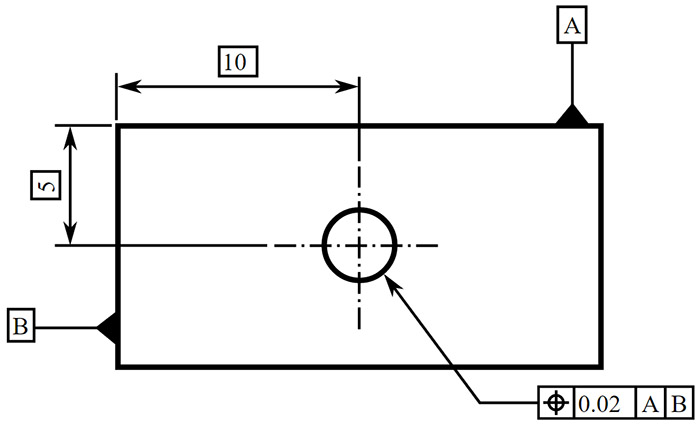
A number in a box denotes a Basic Dimension. Image Source
Given that there is just a number in a box, Basic Dimensions have no tolerances.
Feature Control Frames
A Feature Control Frame describes the conditions and tolerances of a geometric control on a part's feature. A feature control frame contains four pieces of information:
Each Feature Control Frame will typically (it is optional) have a leader arrow pointing to the feature it describes. Consider the Feature Control Frame in the drawing above:
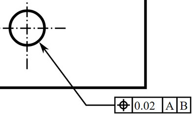
A Feature Control Frame...
The Leader Arrow points to the hole feature. It has a Geometric Symbol, in this case, a Position Symbol. Given that this is a round hole, the tolerance could be a diameter, in which case we'd have a diameter symbol ahead of the tolerance. Instead, we just have a tolerance value, so this is a positional tolerance for the center of the hole. We could follow the tolerance with a Tolerance Modifier. The "A" and "B" are the primary and secondary datum. If we look to the original drawing (top of page) we can see that these tell us where to measure the hole's center from. In this case, "A" denotes the top edge of the part and "B" denotes the left edge.
This is a lot to take in, and we're not trying to completely describe every aspect of Feature Control Frames here. Rather, we are introducing a concept we will elaborate on more fully later in the tutorial.
Datum and Features
As mentioned above, Datums tell us where to measure from. Calling them out clearly and labelling each Feature Control Block with the applicable Datums makes it completely clear how things are to be measured. While a datum may make sense on a drawing, it is important to keep in mind that parts are physical. You could specify a datum in such a way that it is impossible to take the measurement on a real physical part, so always visualize how a datum could be used to inspect the part.
Features, meanwhile, are the real geometric shapes that make up the physical part. Examples include holes, screw threads, profiles, and faces or slots.
Material Condition Modifier
Material Condition Modifiers are used to refer to a feature in its largest or smallest condition, or to refer to it regardless of feature size. There are three Material Condition Modifiers:
- Maximum Material Condition (MMC): MMC might be used, for example, to refer to the largest pin or the smallest hole.
- Least Material Condition (LMC): LMC could refer to the smallest pin or the largest hole.
- Regardless of Feature Size (RFS): RFS could refer to any increment of feature size of any feature within its size tolerance.
Next Article: Rules and Philosophy
GD&T Table of Contents GD&T Symbols


|
Do you want to be a better CNC'er in 37 Seconds? Get Better Tool Life, Surface Finish, and Material Removal Rates Fast. It's that easy. You can install and get results in a matter of minutes.
|
||||||||||||||||||
| ||||||||||||||||||