|
Do you want to be a better CNC'er in 37 Seconds? Get Better Tool Life, Surface Finish, and Material Removal Rates Fast. It's that easy. You can install and get results now. |
Helical Interpolation and Circular Ramping Make Bigger Holes Than Any Cutter You've Got |
Introduction: What is Helical Interpolation?
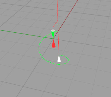
We're all familiar with a Helix, right? Here's a simple helix as displayed in G-Wizard Editor's backplot:

A Helix programmed in G-Code...
What's unique about the helix is that it is programmed via arcs, and each arc specifies a change in the Z axis, which is what leads to the helical shape as the arc both curls and descends. Helical Interpolation is an interpolated motion because it requires simultaneous motion in multiple axes--X, Y, and Z.
When Should Helical Interpolation be Used?
Helical motions are typically used for three cases:
- Making holes
- To create Circular Ramping to get a cutter down to proper depth before machine the rest of a feature such as a pocket
- To perform thread milling.
We'll save the thread milling for another chapter, but the first two applications of Helical Interpolation are pretty similar. Essentially, we want to create a hole that is larger than what we'd get simply plunging the cutter straight down. Why do this instead of just using a bigger cutter? Endmills are not the most efficient tools for making holes if the correct size twist drill is available. You can plunge a center cutting endmill (don't try it with one that isn't center cutting!) to create a hole, but it will be much slower than using a twist drill because that's not really what the endmill's geometry is optimized for. There are several problems with insisting on a twist drill in every case though.
First, it requires an additional toolchange and potentially an additional slot in the toolchanger. You'll need to dedicate a slot for every hole size, whereas a single endmill can interpolate an almost infinite number of hole sizes.
Second, twist drills burn up a lot more horsepower than the equivalent helical interpolation operation--that's the price of going faster, but for a big hole, it may be too high a price depending on your CNC machine's capabilities. Even if you machine has the horsepower, that power will be converted to cutting force which may compromise the machine's rigidity. For a precise hole, interpolation may beat a big twist drill at holding tolerances. Consider a 3 1/2" hole, 1" deep, in mild steel. G-Wizard Calculator suggests this will require nearly 17 HP, and that goes up quickly with hole size.
Third, big twist drills can be very expensive compared to the endmills required to interpolate a hole.
The bottom line is that Helical Interpolation with an endmill is often a better approach than a twist drill, and the larger the hole, the more likely that will be.
Let's talk a bit about circular ramping too. We have an entire chapter in our Feeds and Speeds Tutorial dedicated to CAM Toolpath Considerations that goes into more detail. The short summary is that when a tool is getting down to depth to begin a pocketing or other toolpath, all methods are not equal. Some are gentler than others. Plunging the endmill is the worst. Ramping in a straight line is better, because it is gentler. Circular Ramping, which is basically just making a hole using Helical Interpolation can be even better, especially when cutting deep relative to diameter. This is because ramping down is basically slotting, whereas Helical Interpolation creates a little more breathing room for the chips.
While we're on the subject of chip control, it is important to try to make room for chips to evacuate and to use coolant effectively to clear out the chips when doing Helical Interpolation. If the hole gets too deep relative to its diameter, this becomes harder.
How to Program Helical Interpolation
Here's what the g-code looks like for the helix pictured above:
Z0.2
G00 X0.2375 Y0.0
G01 Z0.001
( Helix down to -0.5 )
G03 R0.2375 X0.1679 Y0.1679 Z-0.067
G03 R0.2375 X0.0 Y0.2375 Z-0.134
G03 R0.2375 X-0.1679 Y0.1679 Z-0.201
G03 R0.2375 X-0.2375 Y0.0 Z-0.268
G03 R0.2375 X-0.1679 Y-0.1679 Z-0.335
G03 R0.2375 X-0.0 Y-0.2375 Z-0.402
G03 R0.2375 X0.1679 Y-0.1679 Z-0.469
G03 R0.2375 X0.2375 Y-0.0 Z-0.5
As you can see, the helix is a series of G03 arc commands. What's unique is they specify a change in the Z axis, which is what leads to the helical shape as the arc both curls and descends. This requires simultaneous motion in all three axes--X, Y, and Z--and is not available on every control. Many controls are also finicky about the maximum angle of the arc--how far around the circle you can program. The most conservative code will only use 90 degree or less arcs rather than try to do a full 360 degree circle in a single line of g-code.
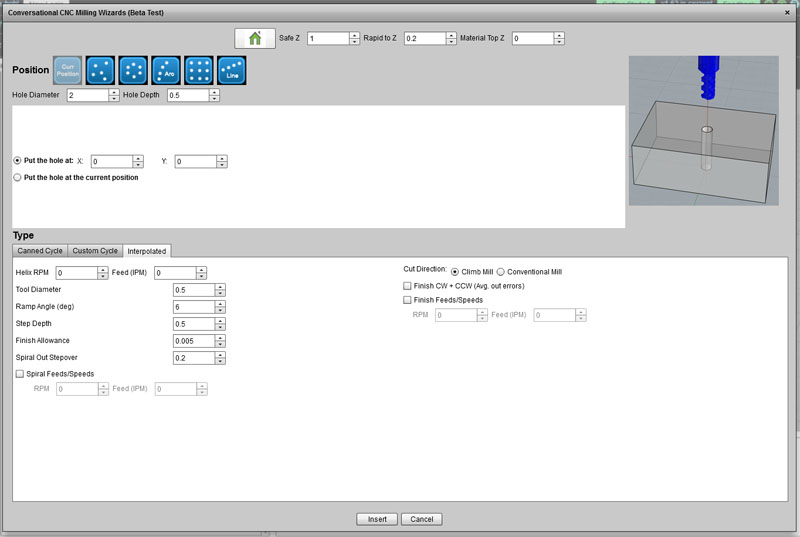
You'll need some math to decide what the endpoint coordinates for each arc will be. I like to use an Excel spreadsheet for such calculations, but there is an even better approach: G-Wizard Editor has a built-in Hole Wizard that has an option to generate g-code for interpolated holes. Here's what the Wizard looks like:

Helical Interpolation with the GW Editor Hole Wizard...
GW Editor's Wizards make a lot of g-code programming easy. Just answer a few simple questions and they'll generate the g-code for you. In this case, we need to know things like the hole location, Z levels (Safe, Rapid To, Material Top, Hole Depth), feeds and speeds, and so on. Click "Insert" after filling in the form and the g-code is automatically created.
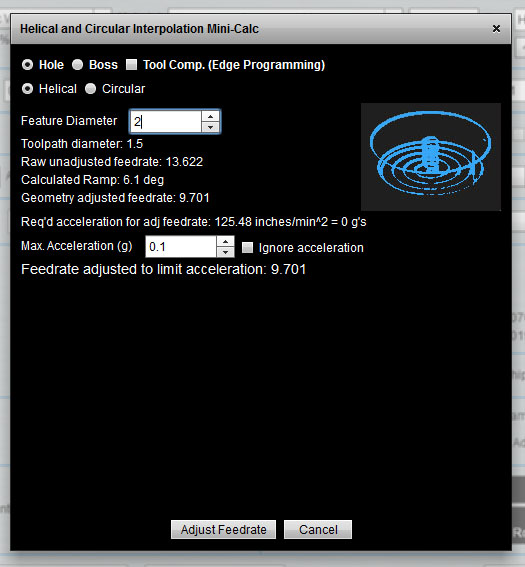
Some of these parameters may not be so obvious. Feeds and Speeds are always an issue, but what about something like choosing a Ramp angle? It turns out you can get help on these from G-Wizard Calculator, which has a special Interpolation Calculator for these things. Here it is set up for our particular example:

Helical Interpolation Feeds and Speeds...
To use it, startout just as though you wanted feeds and speeds for a slot. Give the Machine, Material, Cutter, Hole Depth, and Slot for Cut Width. Then click the "Interpolate" button to see the Mini-Calc. The parameters on the popup set it up for your operation. You can interpolate either a hole or the outside of a boss. The feature diameter together with the information already entered in GW Calculator enable it to further calculate an adjusted feedrate and a preferred ramp angle. It will also adjust the feedrate to move a little more slowly based on how much acceleration is required and on the actual distance traveled. Hit "Adjust Feedrate" and that is all plugged back into your overall Feeds and Speeds calculation.
Conclusion
Helical Interpolation is a valuable technique for any CNC Programmer's bag of tricks. The information in this article should enable you to take advantage of it. Go forth and try it for yourself, Helical Interpolation is neat!
Exercises
1. Set up GW Editor Hole Wizard to create some helical interpolations. Study the code, run the simulator over it, and learn how it works.
2. Try using GW Calculator's Interpolation Mini-Calc to figure the Feeds and Speeds for your Helical Interpolation.
Try the Free Trial Version of G-Wizard CNC Program Editor...
No credit card required--just your name and email.
Next Article: How to Program Tapping on a CNC Machine
|
Do you want to be a better CNC'er in 37 Seconds? Get Better Tool Life, Surface Finish, and Material Removal Rates Fast. It's that easy. You can install and get results now.
|
||||||||||||||||||
| ||||||||||||||||||