|
Do you want to be a better CNC'er in 37 Seconds? Get Better Tool Life, Surface Finish, and Material Removal Rates Fast. It's that easy. You can install and get results now. |
Powered Drawbar for My Industrial Hobbies Mill
Finished Drawbar: You Need One!!!
Here's the beasty perched atop my Industrial Hobbies Mill...
Click this image for a MOVie file of the drawbar in operation: Requires QuickTime!
I don't know how I got by without one, now that I have it. They are available commercially, but I built mine (see below). Boy, does this ever make toolchanges fast! Press "OUT" and the tool pops out into your right hand in about 3 seconds. Insert a new tool in the spindle, press "IN", and the holder or collet is torque down and ready to go in another 3 seconds. I love it!
Details
Some time ago I came across a set of plans for a powered drawbar to be based on an import air impact wrench. The outfit selling them is called Home Shop Accessories, and the price was reasonable, so I sent off for a set. They arrived in fine order as a PDF file in my email inbox. I looked them over, and they were a high quality set of plans. Eventually I would build one of these gadgets and thereby make changing tools in my mill that much quicker. A lot of the earlier CNC mills such as the Tree 325's didn't even have a toolchanger--they relied exclusively on a power drawbar to speed up tool changes. I wanted to achieve a similar advantage for my own mill. There have been some others that came this way before me, such as this fellow, who mounted one of the Bridgeport "Aussie" power drawbars available on eBay:
Pretty soon, the same outfit I got my plans from released an even better version, which they were now calling the world's simplest and cheapest drawbar:
Simplest, cheapest, powered drawbar you can build!
I promptly ordered the second set of plans, and I have to admit this is an amazingly simple design. It was finally time to dive in and start swimming on this project!
You can follow along here and see how I did it, but if you want to build your own, you will need a set of plans because I'm not giving out all the details here--wouldn't be fair! They're cheap and very well done, so order 'em up!
I got a butterfly impact wrench ordered from Harbor Freight, you want the Central Pneumatic 37730. I also ordered the preferred air cylinder from Air Cylinders Direct, as it was the cheapest source I could find and was also the one recommended in the plan set. Other than a few small plumbing fittings to route the air around, you will be making the rest of the parts. The air cylinder was $20 with shipping, and harbor fright charged me $26.99 for the butterfly impact wrench, which is a nice looking piece, BTW.
An air cylinder to raise and lower and the butterfly impact wrench: These are the guts of the powered drawbar.
Top of the IH got me concerned about exactly how clearances would work out, so I made the base plate first, or at least far enough so I could trail fit things. It's covered in Dychem. I used my boring head to cut the semi-circular pocket similar to what I did on my power feed. I also cut out a notch to clear the gearbox oil fill. I wish I had the bigger motor on it, because I won't know how that will affect clearances. Oh well, may have to re-engineer at that point!
Initial stages of the valve backplate. Lots of drilling and tapping on this project!
Need to cut some angles onto the valve backplate to clear the operating lever. The backplate is resting on an angle block in the chuck. I used a parallel to apply side pressure because the angle block is thicker than the piece I'm cutting.
There's one of those angle plates right now. They come in a set. Very handy!
Here we are about finished. I just eyeballed it, gradually increasing depth until the point was roughly centered on the hole. Next, I take my air file to all those pointy corners.
Just got this air file on sale from Enco--it's a mini belt sander. They are awesome for this sort of thing!
Here is the valve mounted to the valve backplate. That's my little rocker handle I milled out of aluminum. My Asian letter stamps don't stamp very clean, do they? But they'll work OK.
Another view of the valve backplate. This gets mounted on the mill wherever you want the drawbar switch to be.
Now here is the plate that the impact wrench is mounted to.
Wrench and air cylinder are mounted up!
A slightly different view...
Turning the rods that the impact wrench will ride on...
To make the top bracket, I used my transfer punch and brass "hammer" to center punch the holes so they'd line up. Transfer punches are handy!
Next comes the fiddly part. You've made the guide rods to proper length, and made all the brackets. Bolt the whole thing together and play with it. When you press down does the wrench assembly slide smoothly? When you release it, is the return spring pressure strong enough to return it to top? Some fiddling with the slide rods helps tremendously. In the end, I didn't have quite enough spring pressure to reliably return the wrench to the top of travel every time. The answer was to drop a couple compression springs onto the guide rods to assist. These were readily available from the hardware store.
Notes to self: Were I to redesign this thing to improve upon it, I think I'd build the springs in from the get-go. I'd also be tempted to find a way to machine some UHMW plastic to serve as the bearing material that slides on the steel rods.
The other thing that was a bit of a nuisance is the top of the IH Mill has a complicated series of concentric round protrusions that have to be cleared before the base will bolt down against the mill head. I wound up simply making my base with slots and having it sit atop the round boss. One could spend a bit more time and make the base so it sits down onto the flat part of the mill top if you wanted.
In any event, I didn't take all that many pictures on this project. As I said, you need to buy a set of plans if you want to build one of these. It wouldn't be fair for me to give it all away. The plans are very inexpensive and there's a lot of good writing there to help you make one of these.
Highly recommended!
Postscript: Ideas I Missed the First Time Around
Socket Guide
Awesome idea from Bohica on CNCZone! I had seen the Tapered Drawbar Bushing (see below) to help keep the drawbar centered in the bore. This helps considerably to reduce the wear of engagement and generally cleans things up. But Bohica's idea was to machine an adapter that would not only keep the drawbar centered but that would also guide the socket right down onto the head of the bolt. Here is his very nice and clean drawbar on his IH mill:
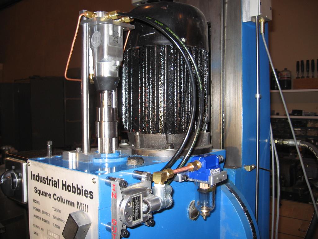
Note the separately mounted air gadgetry, nice and clean. More importantly, check out the socket guide sitting on top of the spindle shaft!
He gives a .DXF drawing in his write up, but here is my own interpretation in Rhino3D:
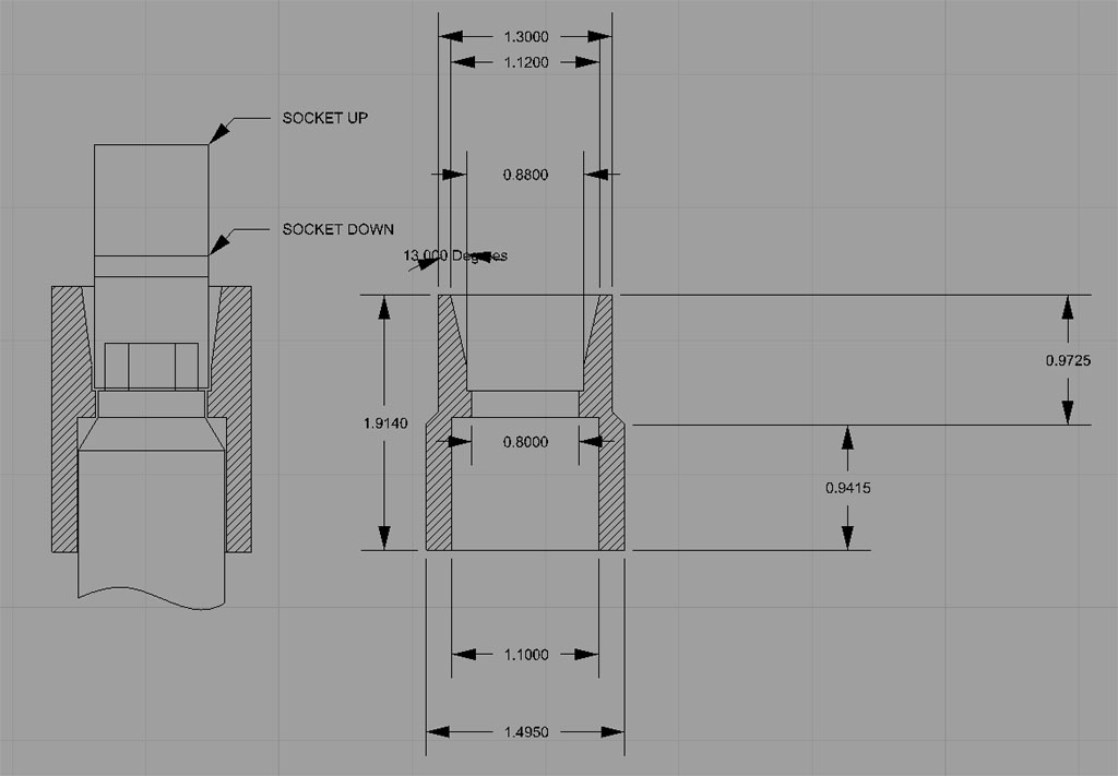
Seeing as how I need to build a pulley that fits tightly onto the splines of the spindle for a belt drive conversion, I think making one of these to fit the splines will be an ideal warm up and test of my ability to make the part accurately. For the finished belt drive, a guide like this will be integral to the pulley assembly that I machine.
Tapered Drawbar Bushing
I came across this idea over on the HSM Board, and I think its great. This fellow replaced his drawbar washer with a tapered spacer that does a better job of keeping the drawbar centered:
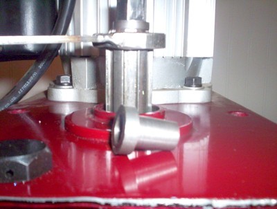
Someone else gave me this idea, here is their version...
Every now and then my drawbar gets cocked a bit and the powered drawbar has to work to engage the socket to it. It manages, but a bushing like this would make things run more smoothly.
Update 1/26/07: I made my own spacer. It took all of a half hour. Boy, what a difference! I made mine to fit fairly snugly in the spindle and leave a nice easy fit for the drawbar to go in and out. The drawbar is now very closely centered every time, the spindle seems to run more smoothly (better balanced or just my imagination, who knows?) and it was well worth doing. I am updating the drawbar page to reflect that this is a "must have" part of the project. I think it will reduce wear on the drawbar nut since the socket will be closer to right on.
Don't Want to Deal With Building a Drawbar? Two Options...
Option #1: Handheld Impact Wrench
Just buy the HF wrench and use it by hand. I've done that on my CNC mill since I haven't yet built a drawbar for it as I write this. Works great and is superfast. Just reach up with the imapct wrench in one hand, grab the toolholder in the other, squeeze the trigger and boom, the toolholder is out.
Option #2: Buy someone else's
I saw this on eBay recently:
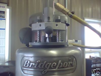
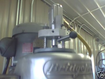
It's a little simpler design. Looks like you are meant to move the drawbar down by hand instead of with an air cylinder and rotate the handle to control the wrench. $195 from eBay seller mad_season74.
2nd Generation Powered Drawbar
The first version I built works great, and is easy to build. This second generation (which I haven't built) is just some thinking about alternate designs. I've got 2 mills and will eventually build a drawbar for the 2nd (CNC'd) mill that is integrated with the belt drive components.
Meanwhile, food for thought:
Guts of a Kurt power drawbar are built on a Chicago Pneumatic butterfly impact wrench. The air cylinder is machined into the base...
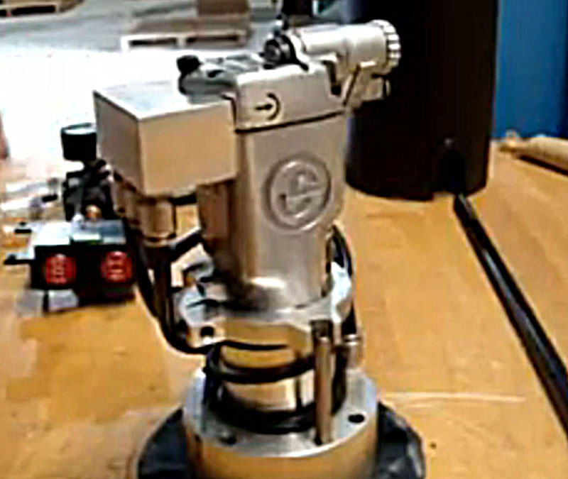
Note how the butterfly impact wrench is clamped. Looks like the air block is attached via the swivel for the old wrench activating lever...
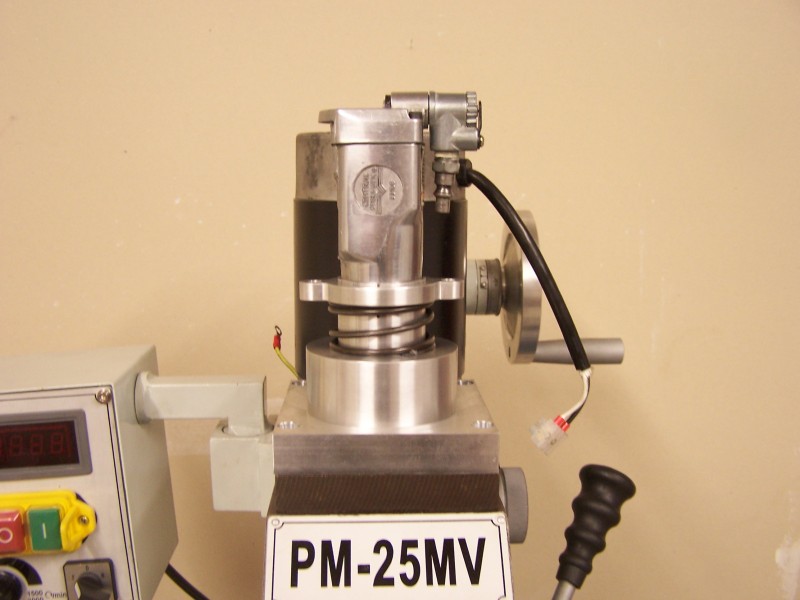
A copy of the Kurt Starleper is building...
I like this Kurt-style design because its more compact. It would be more trouble to build, since you have to machine the air cylinder/base, but perhaps not too much more trouble.
Be sure to check out G-Wizard, our Machinist's Software!
|
Do you want to be a better CNC'er in 37 Seconds? Get Better Tool Life, Surface Finish, and Material Removal Rates Fast. It's that easy. You can install and get results now.
|
||||||||||||||||||
| ||||||||||||||||||