|
|
|
|
|
|
|
Do you want to be a better CNC'er in 37 Seconds? Get Better Tool Life, Surface Finish, and Material Removal Rates Fast. It's that easy. You can install and get results now. |
 |
Lathe Drilling, Boring, and Reaming Notes |
Herein are my notes on drilling, boring, and reaming holes. Many of them are relevant to mills too.
They are to date a rather disorganized collection of anecdotes found elsewhere. Over time I will organize these and test each one, discarding those that don't work so well and emphasizing those that do. For now, I am using a font convention to differentiate the tips:
If I have written a tip in this font, I have personally verified it.
If it is written like this, I found it on the Internet and am awaiting verification. These are the ones to take with a grain of salt.
| Accurately Locating and Drilling Holes |
If you are just wanting to layout within +/-.030"then a good scale and a sharp pencil are fine. But if you desire closer tolerences then more precison is needed.
Typically if all I need is +/-.005" I will cover the area where I will be marking with marks-a-lot and then use my calipers as a scribe and work off the edges of the part.
If greater precison is needed,then stock preperation is needed first,all edges need to be square in relation to each other and the edges need to be smooth and straight.
The tools to use then would be a surface plate,a hieght gauge,machists squares,angle plates and etc.Learning to use these +/-.0005" is possible in the homeshop.
--------------------------------
The real challenge then is drilling the hole where you want it. A
sharp prick punch helps mark the hole but can be off by as much as 10
thousandths. An optical punch can reduce this to under 5 thou. Then you
need a tight setup to hold the work and move it around til the punch mark
is centered under the spindle.
This is where milling machines have it over drill presses. Use of a spinner
tool helps to center the spindle. Then the pilot hole should be drilled
with #3 or 4 centerdrill, depending on the ultimate hole size. For 1/2"
holes in al you could probably just go to the 1/2" drill size, but
a better method, almost mandatory in steel is to drill a pilot hole at
least the thickness of the drill web first and then go to the final size.
The center drill deflects very little compared with standard drills. Try
putting a 1/4" drill in the DP or mill and punching a good solid
drill punch marker in al or steel and see how much the end of the drill
can deflect when you are off center 10-15 thou. The end of the drill bit
just slides down the conical side of the punch hole and bends the drill
slightly. Center drills will do this too but not nearly to the same extent.
---------------------------------
Measure off "one" side or a known square side if possible.. We never get perfect cuts off the cheap arse saw I have. The lil notch in the end of the square is there for a reason.. You can lay a pencil in it, stroke the square down the square side of stock and you have a parallel line to the edge. If you have another side on the stock that is squared off, you can do the same there. The lil scribe in the craftsman square is there the for laying out perfect lines, but when you pull it half a dozen times it falls out and is lost. A tri-square, sometimes they are not square. A box square always is, till you lay it on tubing with a radius'ed edge, then it can follow the edge and not be. To measure something, you have to have a known point to measure from. (one flat edge.)
------------------------------
Personally, I locate holes using the X-Y travel of my milling machine.
I do layout first, but only as a guide to provide a check on where I'm
drilling. But if you are locating/drilling ONLY from layout, the first
thing to do is probably to establish a reference edge, from which you'll
take all measurements. Then put some layout blue on the surface of the
workpiece and with a sharp scribe and steel scale, carefully scribe locating
lines. Magnification helps. Then with a sharp prick punch, make a tiny
mark at the intersections. Check locations with a magnifying glass. If
slightly off, you can move the location of the prick mark over by tapping
the punch at an angle. When looks as good as you're going to get it, make
the mark deeper.
When you go to drill, locate each prick mark under the spindle in turn
with a "wiggler," then switch to a center drill and drill a
pilot hole.
One book that describes the process is the Starrett Book for Student Machinists, which I imagine is still in print.
------------------------------------
In regards to marking and drilling accurate holes. I am suprised that nobody mentioned "toolmakers buttons". With these you can drill and tap a small hole where you have prick punched then attach the buttons. You then mike over the buttons in all directions and adjust them to the correct location. Once this is done you can indicate the the button true to your spindle,center drill then drill to the correct size. Move to the next button and do the same thing. Oh I forgot to mention that after indicating you remove the button before drilling. This will work well for the guy who has minimal machining capacity such as a drillpress with no way to adjust the work.
------------------------------------
If you scribe your lines with a very sharp point you will leave a very fine "X". This "X" serves as a guide if you have a sharpened center punch. It's actually possible to get them perfect in the dark simply going by feel of the scribed marks. When you're dead on, the punch tip is very stable and won't slide around on the work when you try to wiggle it. Make sure the punch is as vertical as you can make it and then give it one good rap with a hammer. Something I discovered late in life is when you are making stuff up on your own, always use a standardized measurement. As an example, mark all holes to be drilled on multiple's of 1/8th inch. That way, if you have to repeat some holes a year from know you will know that the center of the hole is likely to be 7/8's and not 15/16th's I use to do it just randomly and then had trouble makeing mating holes. By the way, you can buy really fat magic markers that work good for "blueing" the area you're going to be marking on with the scribe. I would suggest you use a scribe when measering for metal or wood. It makes a finer line and causes you to work more critical. A line has three components when you are going to try and cut it. It has a right, left and center to it. Usually if your making inside measurements you leave the line on the finished cut. On outside measurements you take the line. If you are measuring with a tape then it's all up in the air unless you can really mark precisely and indicate with an "x" on the material which side of the line is waste.
--------------------------------------
I read through these posts, and didn't see anyone mention how to move your center punch mark. Let's say you've done the layout, and with a light tap punch the mark. Then you discover it ain't where you intended, exactly. By healing over the end of the punch, and tapping some more, you can move the mark. When you're satisfied that it is indeed centered, then it can be deepened. Personally, I'll use a fine punch with a 60* point for layout and 'placement correction', then switch to a heavier punch with a flatter angle (118* maybe?) for that final whack. A drill will walk out of that 60* dimple sometimes. All I'm saying is, you don't have to take a crappy punch mark laying down!
--------------------------------------
I use a magnifying lens to help position the punch when marking the holes for drilling. My two usual methods- one is to use a sliding square and set it for the required distance from an edge, then pencil mark. Mark all equal distances from an edge without changing the setting. Then reset it for the crossing lines to mark holes, then mark all at that distance. Then squint and curse and spin around to try getting the light just so, then I can see my marks. Using a magnifying lens, position the punch and mark the location. Second method is to use the caliper to scratch the marks, then carefully feel for the crossing of the marks with a sharp punch, using the magnifying lens as well. Same squirming about to get the light just so- The trick here is the use of the magnifying lens. No-one mentioned it, so I did. It's actually pretty easy to mark a hole to within a few thou using scribed lines if you can actually SEE where you're putting the punch. Combine vision with the feel of the point in the scribe marks, and you'll get very close. I like to have a good solid backing as well, so the punch marks are made very crisply. Now for what this has reminded me of, yet again. A lighted, magnified center punch project. That would get a lot of use in my shop.
--------------------------------
Thoughts from Swede on drilling 1/16" and other small holes that must have accurate fits for making model engines:
Having holes go oversized is not uncommon, and as you noticed, a misalignment can in fact cause them. Aluminum especially tends to drill oversized, especially when the hole is deep. One way to avoid a small hole (in a small part) from going large is to drill it first perhaps 8 or 10 thousandths shy of the target, then remove it from the lathe. Switch the job to a drill press, and drill out the final hole by allowing the part to "float" a bit and find its own center. Another technique - if you've ever actually miked a small, wire-gauged drill, you'll perhaps have noticed that they mike slightly smaller than the hole they are supposed to drill. All drills actually cut a hole physically larger than the space that they occupy, otherwise, they'd simply stick in the hole! I hope this makes sense. The drills are ground to a specific dimension with the knowledge that the hole they will cut will be ever so slightly larger than the physical size of the drill. This effect, as a %, is more pronounced in the small wire gauge drills than a heftier drill bit. What this means - If I have the mating part or pin, I'll often try sneaking up on the final hole by drilling it out one or two wire gauge sizes smaller, and physically checking with the mating part. For example, rather than drill straightaway with a 1/16" drill you might try a #53 first. If that works, you're done. If not, proceed to the 1/16" drill, and since you've pre-drilled, the subsequent hole should be closer to 0.0625" rather than oversized. HTH - I really can't see the need for a 1/16" reamer. If you ultimately need to make a 1/16" d-bit or other homemade cutter, you might want to try a nice little piece of 1/16" music wire, and simply grind a 1/2 flute into the tip with a dremel cutoff wheel. It won't last, being spring-tempered carbon steel, but it should ream a hole or two in aluminum or brass. One last option - take a 1/16" drill bit (they're cheap), chuck it in a drill press, and lightly apply a fine diamond or oil stone to the drill's flutes while it's spinning. You'll probably ruin the drill bit, but it's possible that a light stoning like that might cause it to drill 0.0005" or 0.001" less than it normally would. Obviously use it in a pre-drilled (undersized) hole, and check the outcome on scrap first. Good luck!
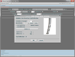
| Depth of Cut With Boring Bars |
Use as a minimum 60% of the tool tip radius. 1/64" radius gets 0.009" DOC.
| Sharpening Drill Bits |
Geof on how to hand sharpen a drill bit:
Step one; turn the bench grinder on. That is the really easy part. Look closely at the drill and note the cutting edge is a straight line. Hold the drill so that the edge you intend to sharpen is facing up and parallel with the shaft of the grinder and very close to the wheel; NOT touching yet!!!! Imagine a radial line drawn from the center of the shaft to the cutting edge of the drill and project this line out for about the length of the drill. Because the cutting edge of the drill is parallel to the shaft of the grinder the drill and imaginary line will form an angle that depends on the point angle of the drill. Now imagine you are looking from the side; the centerline of the drill itself should be below the radial line by around 3 to 5 degrees. This is what starts your initial clearance angle on the cutting edge. 'Looking' from the side is necessary so you 'see' the projection of the radial line onto the drill centerline. So far things have been easy; now you go into imagination overload but first a little explanation. If you simply brought the drill into contact with the wheel in the position it is currently held the cutting edge would be ground okay but further around there would be insufficient clearance; the 'heel' of the drill would rub. You need to be able to grind heel clearance. Now imagine a line that runs parallel to the cutting edge of the drill but which is located about 1/4 to 1/2 the drill diameter back from the edge and about 1/8 to 1/4 the drill diameter below the level of the cutting edge. You are going to rotate the drill around this line with the cutting edge moving upwards. Naturally if you just did the simple rotation the cutting edge would rotate up and away from the grinding wheel so it is necessary to move the axis of rotation down and closer to the wheel simultaneously with rotating the drill around the axis. This is the hard part; it is difficult to describe other than to say the cutting edge of the drill performs a sort of 'scooping' motion. The radius of the the scoop and the depth of the scoop determine the heel clearance on the drill but if you scoop too far you hit the opposite cutting edge against the wheel and destroy its cutting edge. And once you have perfected this for one cutting edge you do the other exactly the same.
|
Do you want to be a better CNC'er in 37 Seconds? Get Better Tool Life, Surface Finish, and Material Removal Rates Fast. It's that easy. You can install and get results now.

|
||||||||||||||||||
| ||||||||||||||||||