|
|
|
|
|
|
|
Do you want to be a better CNC'er in 37 Seconds? Get Better Tool Life, Surface Finish, and Material Removal Rates Fast. It's that easy. You can install and get results now. |
Eliminating Backlash, Part 1: Basics
If you're looking over this page, I'll assume you wonder why you should eliminate backlash (or how much can your stand), you want to build a CNC machine from scratch, or you are converting a manual machine that has measurable backlash. If you have a machine already converted that has the "good" parts (like ballscrews), and still have too much backlash, try Part 2 for ideas to solve your problem.
What is Backlash?
According to the CNC Dictionary, backlash is any kind of unexpected play in an axis due to clearance or looseness of mechanical parts. When the axis is commanded to move, the drive motor may turn briefly before movement begins. That delay is the backlash.
Backlash has a variety of causes. The most common is play between the leadscrew threads and those of the nut. ACME screws can have considerable backlash of this kind, while ballscrews may have almost none. Another source is any tendency for the screw to move axial in the bearings that hold it, or any other such play in the system. Precision angular contact bearings with preload are often used to combat this tendency. Gears, belts, and chains can all introduce backlash into a mechanical system. Even loose fasteners or flex in the mounting plates or chassis can be a source of backlash.
Why Eliminate Backlash?
Backlash is a subject that comes up frequently in CNC machine discussions, and it seems machine makers are willing to go to no end of trouble and expense to eliminate backlash. Why is it considered so bothersome?
There are several reasons. First, CNC machines are largely blind and even most closed loop systems lack much ability to sense that the axis hasn't moved even though the motor has. A system that has both encoders on the shafts and some form of linear encoder may be able to sense the axis hasn't moved, but even a machine that "knows" the backlash is there suffers from the other problems.
A second issue for backlash can occur while climb milling (for a definition of climb and conventional milling, try the CNC Dictionary). Climb milling is often preferred to conventional milling because it produces a better surface finish and places less stress on the machine and cutter. However, if an excess of backlash is present, the action of the cutter can operate to pull the workpiece suddenly into the cutter by a distance equal to the backlash. At the very least this is counterproductive to surface finish and at the worst, it can result in a broken cutter, scrapped workpiece, or even injury to the operator from flying debris. Very bad! Clearly this one doesn't go away even if the machine knows how to compensate for the backlash. The benefits of climb milling are so great that even some of the later manual milling machines at the high end came with ballscrews or "backlash eliminators" just so climb milling could be practiced on these machines. You can still buy retrofit kits today to add ballscrews to say a Bridgeport mill for this purpose. If you don't plan to CNC the machine, make sure your ballscrew installation is properly spec'd to avoid "back driving". This is where the friction on the ballscrew is so low that it won't hold the table in place against the cutting forces. It's largely a matter of specifying the right lead for the ballscrew or in some cases have a friction mechanism on the axis that can be engaged and disengaged as needed.
The last issue is one of smooth continuous machining when direction is reversed. It's possible for a CNC machine to do things a manual operator spinning the handwheels could never do, like cutting a smooth circle. The operator needs a rotary table to do this, but a CNC machine can smoothly operate two axes precisely enough to generate a circle, unless there is backlash. It turns out a circle forces several changes of direction throughout the course of the cut. See the Stepper/Servo/Backlash Simulator for more details of this, but here is an example of what such a cut looks like when there is backlash:
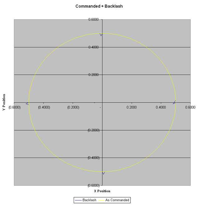
Backlash "Ears": 1" diameter circle, 0.020" backlash on both X and Y axes...
The little kicked out "ears" happen at each point an axis changes direction on the circle. You can imagine also that when a part is being profiled, the spindle is moving back and forth and up and down to follow the contours of the part. Every time the spindle goes down and then shifts back up, that is a reverse of direction. Backlash is going to cause inaccuracy or dwell marks at those points where the direction is reversed.
As a matter of fact, cutting circles is an acid test for a mill. Try one and see how it turns out to get a rough idea how your backlash is doing as well as a number of other factors.
It's worth noting that lathes have it a lot easier than mills where backlash is concerned. There is no equivalent of climb milling on a lathe, and a reversal of direction need not occur smoothly while cutting as often.
Lastly, the CAM software you'd like to use to generate your g-codes assumes your machine has no backlash. It doesn't produce code that operates the machine the way a manual machinist sensitive to avoiding backlash problems would.
Okay, hopefully we've made a believer out of you that you want to get rid of backlash. BTW, for some applications, such as plasma cutting, the resolution needed may be so low that quite a lot of backlash is acceptible. Try to keep that in perspective as well.
What About Backlash Compensation?
When a manual machinist is faced with backlash, he naturally follows a routine that for the most part allows him to ignore it. That routine involves taking up the slack (or backlash) on the handwheels before beginning to cut. Machine control software such as Mach 3 can automatically follow the same routines for backlash. It isn't quite as good as the operator, because it lacks his "feel" of exactly when the lash is gone and instead relies on being told how much backlash is present. It's very hard to get that exactly right and it may change as your leadscrew wears or your machine needs adjustment (for example the gibs need adjusting). Remember also the problems with climb milling and reversing direction. Our manual machinist probably avoids both because he knows he'll get into trouble. We're not getting full value out of our CNC machine if we force it to avoid climb milling, cutting circles, or the host of other operations that involve changes of direction during a cut.
So, backlash compensation is a weak bandaid for the problem. It's better than nothing, and may tide you over until you break out the checkbook and fix your backlash, but it isn't something you'd probably like to live with long term. If your machine is a lathe, you may be able to live with just backlash compensation.
How Do I Measure the Backlash in My Machine?
Okay, next question. How do I know how much backlash I have? A DRO is handy if you have one, because it will directly measure how far the axis really moved. Failing that, put a dial indicator in the spindle (attach one with an Indicol or similar and don't turn the spindle on for Heaven's Sake!). Set it up to read against a 1-2-3 block or other flat reference, put a little tension on it with the handwheel (or manually jogging a CNC machine) to get a reading, and zero the indicator. Now move the axis in the direction that takes the tension off the indicator a distance that is greater than any possible backlash and read that off the handwheel. Turn the handwheel in the opposite direction exactly the distance you read off from the first movement. Check your dial indicator. The amount it did not get back to zero is your backlash.
A DRO will directly measure the distance travelled, and when I first got my Industrial Hobbies mill, I measured 0.010" of backlash on the X-axis using my DRO.
Sources of Backlash in Conventional Machines
Okay, so where is that backlash coming from and what's it going to take to eliminate it?
In all likelihood, the majority of your backlash is coming from your leadscrew and associated nut. Most manual machines will use an ACME leadscrew. Because of the nature of these screws, if the nut is made tight enough to eliminate the backlash, it introduces too much friction and the screw becomes impossibly hard to turn. In addition, the nut is often made of a material that wears more rapidly than the screw, so that it may be replaced more cheaply than replacing the leadscrew itself. Such nuts often have an adjustment to take out some of the excess backlash as they wear. When they don't or when they're not adjusted properly, or when all the adjustment is used up on an old heavily used machine, you get lots of backlash. It is not unusual to see backlash of 0.005" on a good quality manual machine with ACME screws, and that figure can easily deteriorate to 0.025" or worse on a badly worn machine.
There are other sources too, such as the gibs or the mounting of the nut or screw. There can be play in how a handwheel or motor is attached to the shaft as well. Since the leadscrew is the biggest source of trouble, we'll consider leadscrew alternatives first.
The "Good Parts": Leadscrew Alternatives
The most commonly discussed alternative to a conventional ACME leadscrew for CNC use is a ballscrew. Ballscrews are typically intended for CNC work, and so are made to minimize backlash. Because they turn with a lot less friction than an ACME screw, they can be built to much tighter tolerances. Ballscrew come in rolled and ground flavors, with the latter being more precise and more backlash free. A decent rolled ballscrew will deliver 0.003" backlash while a poorly made one has perhaps 0.010". A ground screw ought to be no more than 0.001" and probably should be less. There are ways to reduce this further having to do with the nuts and preloading of oversized balls, which I'll talk about below.
Besides ground versus rolled, ballscrews come in different accuracy grades that you should be aware of:
C0 - 3um or 0.0001" per 300 mm / 12"
C3 - 7um or 0.00027" per 300 mm / 12"
C5 - 14um or 0.0005" per 300 mm / 12"
This refers to how close the position will be after the screw has turned through 12" of motion. Note that in this area, there are ACME screws available that are every bit as accurate, so the ballscrew has no special advantage here. Another thing to be aware of is that a lot of machine control software, including Mach 3, has a feature known as "ballscrew mapping". This feature lets you measure the true position reached at various points along the ballscrew and use it to compensate for errors in the ballscrew. This function works very well, and should be taken advantage of if you have the means to accurately measure the deviations. This alone is a good reason to install an inexpensive DRO at least temporarily on your machine until you can get the compensation tables calibrated.
It is also interesting to note that this error can vary as the temperature changes based on the room the machine is in and how hard its working. Companies such as Heidenhain sell special controls based on linear scales (i.e. scales like a DRO uses) that dynamically compensate for such errors on very high accuracy machines. It's quite interesting to read their technical articles about this and gain an understanding of how much error can accrue from such factors as temperature variations. The effects of a fully warmed up machine over the full length of the ballscrew was about 0.004", which is significant to many applications.
There are some alternatives to ballscrews that I won't discuss here. They're not seen very often, and you can research them on the web if you like.
Nuts, Nuts, and more Nuts
Lots to know about nuts and backlash. First, you can get nuts made to reduce the backlash of an ACME screw? Wait a minute, you say, we just spent all that time hearing you can't do that without getting too much friction, what gives? Well, it turns out that if you make the nut from Delrin or similar low friction material, you can pretty well get rid of a lot of the normal ACME backlash and things work well for a time and with limited cutting forces. I feel this is a good solution of something like a plasma or router table, but I'm skeptical about how well it would work if you need high cutting forces, for example, to cut metal. In addition, such nuts will wear out rapidly and need to be protected from chips and other contamination.
Secondly, one can arrange a scheme whereby there are two nuts with a spring (such as a Belleville Washer) between them to preload the backlash out of the system. This works for ballscrews, and it also works for ACME screws, albeit with a lot more friction. This is normal approach to eliminate backlash with ground ballscrews. It adds a fair amount to the cost, but is worth it.
The last trick is to load the ballscrew with some oversize balls to take out the slop. This is the normal approach to fine tune a ground ballscrew, and it will work to an extent with rolled screws, but there is a problem with the latter. Since rolled screws are not made to the same degree of precision as ground, too much preloading with oversized balls can lead to binding. The grooves are simply not laid out precisely enough to use this method to eliminate all the backlash.
Using these techniques carefully, one should be able to get the backlash in the ballscrew itself down to the tenths level (0.0001" to 0.0005") or perhaps less with a very high quality screw.
Mounting the Leadscrew and Nut Properly: Angular Contact What? They Cost What?!??
Now you've get a ballscrew with either double nuts or preloaded properly with oversized balls. The next step is to ensure the ballscrew is mounted properly. Unfortunately, this is neither an easy, nor particularly inexpensive thing to do. By design, ballscrews are intended to be secured at their driven end by a pair of angular contact bearings. The other end of the screw is either left to float free in some designs, or secured by a bearing in such a way that if the screw expands or contracts due to heat, it has the freedom to do so at this end. The two angular contact bearings are typically installed in a preloaded configuration which holds the ballscrew firmly and prevents any motion along the screws axis, but still lets the screw turn freely when driven. There is a lot to know to propely design and build a ballscrew mounting of this type!
First thing is to get familiar with the bearing maker's literature on angular contact bearings:
It's really not all that painful to read through these documents, and there is a lot of good interesting information there. If you learn nothing else, be sure to study the standard nomenclature used to identify these bearings. If you're going out fishing on eBay or the Internet to find them, you've got to know how to identify what you're looking for or looking at.
Now given those resources, we can start to explore some of the issues, or at least some rules of thumb that can be used in this area. First, how does the double bearing mounting look and work? Here's a basic schematic representation:

Mounting a Ballscrew with 2 Angular Contact Bearings...
Note the crossed lines. These are the contact angles for the angular contact bearings. Because they are opposed, this provides the resistance to back and forth motion along the axis of the ballscrew. In addition, the bearings are preloaded to take out any internal slop. The preload is provided by the spacer between the bearings, the shoulder of the ballscrew, and the lock nut that is threaded on the end of the ballscrew and bears against the other end of the bearing pack. The ballscrew shoulder and locknut bear on the inner races of the bearing, while the mounting block and cover bear on the outer races. The torque on that nut establishes the preload, and all of these surfaces need to be finished with some fair precision if the end result is to work precisely. The cover is simply holding the bearing assembly in place with respect to the machine, but it does need to be tight with respect to the outer races, so some shimming or spacers may be required.
In this case I have shown the two bearings mounted in the DF, or duplex face to face configuration. The pressures against axial movement are outward, and you can see the bearing balls are supported in that way. You can reverse both bearings to create a DB, or duplex back to back configuration. This still works, and in fact, the bearings will be even stronger at fighting axial movement. The advantage of the DF configuration is that the assembly can tolerate misalignment a lot better, so this is the recommended configuration in this application.
Okay, let's assume you've carefully perused the bearing literature, you understand the way they're to be employed, how do you select the best bearings for your application? There are a number of selection parameters to consider:
| Bore Size | You're going to want a bore that works with your ballscrew. In all likelihood, you may have to turn and thread the end of the ballscrew. You want as precise a fit as possible for best accuracy. The larger the bearing, the stronger it is likely to be as well, though you can check the specs to see for sure. You can't run the ballscrew inside a sleeve to make it fit a bearing that's too large and hope for any accuracy, however. | ||||||||||||||||||||||||||||||||||||||||||
| Contact Angle | Remember the crossed lines above. The greater the angle, the stiffer and better the bearings will be. 15 degrees is the low end of the scale, 60 degrees is the high end of the scale. | ||||||||||||||||||||||||||||||||||||||||||
| Preload |
More is better. You shouldn't exceed the recommended preload of the bearing, but bearings are made to different preload specs. Get the ones with more preload for this application. It is amazing how much preload can be beneficial in eliminating as much backlash as possible. Think 500 lbs and up if you really want to control backlash to minute levels. A typical 15 degree contact angle bearing with high preload might only tolerate up to 125 lbs of preload. Alternatives: You can concievably stack 4 bearings instead of 2 in order to do better, but I confess I do not know much about this higher level of vodoo! In addition, while I said not to exceed the preload, if you have a cheap set of bearings (not a $1000 set!), you might experiment with creeping up on more preload. The downside is that it is going to introduce friction and wear that at some stage may be self defeating. |
||||||||||||||||||||||||||||||||||||||||||
| Quality, Accuracy, and Tolerances |
The bearing is going to have some slop in it. The higher the accuracy rating, the less there will be. Here is the secret decoder ring:
There is at least one highly regarded low end CNC mill being sold today that uses ABEC3 bearings to mount the ballscrews. OTOH, if you want the best, ABEC 7 is the way to go. Note how small the actual differences are between these two grades: 0.00008" runout vs 0.00003" runout. Half a ten thousandth! I can see why for many applications the ABEC 3 works well enough. You need to decide what will be good enough for you, as this particular specification drives up bearing prices faster than anything else. It's easy to pay $1000 or more for a set of ABEC 7 bearings. |
||||||||||||||||||||||||||||||||||||||||||
| Axial Load Rating | If your bearing manufacturer offers this number, you've got the diving rod right there. This is the measurement of what it takes to cause axial motion with the bearing. You want the biggest honking axial load you can get! |
Understanding Angular Contact Bearings Specifications for Ballscrew Applications
When it comes to mounting these little jewels, keep in mind that you probably want ground spacers between the two bearings and the preload nut probably wants to be ground as well. All that can be done for you by a qualified shop, or in some cases you can purchase the parts already ground. Try to buy your bearings as a matched pair (they'll say "DUL" or "DUH" in the bearing name) and they won't need the spacer between them either. As mentioned before, you may need to shim or spacer the bearings in the mounting block to make sure they're properly locked in there on the outer races. You will also want some form of dust seal to keep the junk out of your bearings. Here is an exploded view of a professional ballscrew bearing block:
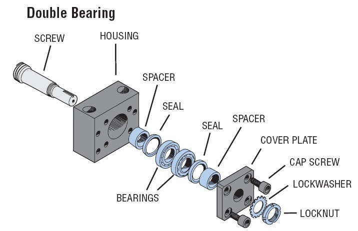
Note that the spacers shown here are not for preload, they simply allow more bearings to be mounted in the block for even greater stiffness, or different spacers would allow some bearing substitutions. Also note that this block has the bearings mounting in DB configuration, rather than DF.
I suspect when you first start shopping for these bearings, particularly if you set out looking for ABEC-7's, your initial reaction is going to be one of discouragement. Great bearings are really expensive. It's easy to spend $1000 without hardly getting started. Your application may justify it, but most don't. Here's a couple of less expensive compromise bearings I came across that are worth looking at:
7204CTDULP4 : $200 for a duplex pair by Nachi (good name) that can be run in DF config, and are ABEC-7's. The downside? There's only a 15 degree contact angle and the preload is light. Still, not a bad starting point.
7204 : $200 too much? How about $24 each for ABEC3's? The downsides--they're not ABEC-7's and they're not a matched duplex pair. OTOH, they have a better contact angle at 40 degrees. Can't tell from this what the preload spec might be, which is bad. Note that what they're calling it, just "7204", is an incomplete desription by bearing nomenclature standards. It would be like calling a person "Frank". If you know there person well, you know which Frank, but in this case "7204" only tells us the size of the bearing. There's a lot we don't know about these bearings, and most of it is probably to the detriment of performance. You don't want to just go ask for a "7204". Read the information above and learn how to fully specify your bearing if you want the best performance.
What if you do want the all the performance possible? Try to find some bearings such as "7204A5TYDUHP4". They'll have a higher contact angle and preload than the "7204CTDULP4" bearings I mentioned, which as we've discussed makes it a better choice. The real expensive bearings, the ones designed for ballscrew applications on machine tools and used by pros, would be something like "20TAC47BDF". That nomenclature is a little different, but you can find them out there in the bearing catalogs. They won't be cheap, but they have a huge contact angle, 500 lbs of preload, and they are ABEC-7's. Don't expect to find the 20TAC's sitting in an eBay auction or expect to buy them from a skate bearing supplier. You might get lucky, but it's unlikely in the extreme. Get ready for some sticker shock on the price, but if they're what you need for ultimate performance, that's what it takes. Many bearing manufacturers keep these types of bearings in a separate "precision" or "machine tool" bearing catalog. Be sure to sniff around their web sites for those catalogs to see what these bearings are and to learn more about how to employ them in this sort of application.
There are endless combinations and trade offs. Shop carefully. Your mileage may vary, and by all accounts, you do get what you pay for!
The other end of the ballscrew can be left unsupported, and indeed has been in at least one CNC mill out there, but this limits the speed you can drive the ballscrew without whipping. In this case, support it with a normal deep groove ball bearing such as you would use on an electric motor shaft. It's not providing precision, it's just providing support and the leeway for the ballscrew to expand and contract axially with temperature changes.
I Want to Use Cheaper Bearings Instead of Matched Duplex Pairs
This can be done. The matched pairs have simply had either the inner or outer race ground so there is a differential size between the inners and outers and preload can be had by compressing the shorter of the two until the races from the two bearings are in contact. One can achieve the same effect by using spacers on one or the other race (but not both!) to create that differential instead of grinding. Doing this is going to require a certain amount of skill and perhaps a lot of trial and error.
The first step is to measure the bearing race deflection with a given amount of preload. Use the amount recommended by the bearing manufacturer for these bearings. This given amount can be placed on the bearings using weights. Measure how much the races deflect with that amount of weight, and then make yourself a spacer with the same thickness.
For a DB configuration (stiffest configuration, but most alignment sensitive), you will be shimming the outer bearing rings. For a DF configuration (less stiff, but more tolerant of shaft misalignment), you will shim the inner bearing rings.
A variety of things can be used to make the bearing spacers, but they need to be very flat, and they will be very thin. In a pinch, aluminum foil could be used, but you'll need to carefully cut it to the correct size to serve. A more elegant solution is to draw up the appropriate washer shape in your 2D CAD program, send it to a laser cutting house, and have them cut washers out of shim stock. You'll want to get some in 0.010", some 0.020" and some 0.002 and 0.005's. Be sure to consult your bearing handbook to make sure the washers are sized properly before you have them made up.
A note of warning: don't try to set preload by a torque wrench on the nut you're tightening or some sort of calculation on the force that nut delivers! It is almost impossible to get it right. A lot of the force is eaten up as friction, and you will not have enough data to do proper preloading this way. The required information is held closely by the bearing manufacturers. When properly installed, tightening that nut will just tighten down the races on the shoulders and spacers. The nut will come to a stop when things are tight and you should not over tighten further.
A second warning: don't think you can get the preload right by feel. It is very easy to damage your bearings this way!
You really do have to rig up a test rig with weights and measure deflection!
You should also make sure the bearings are not fit too tightly on the shaft or in the bearing block. A hand slip fit is all you need! Too tight a fit can damage the bearings or make it impossible to accurately set preload.
For more thoughts and details on angular contact bearings, check out my mill belt drive spindle project page.
Align the High Spots When Installing the Bearings!
I want to stop here and mention an important point, particularly if you are about to disassemble a ballscrew mounting assembly. Be sure to record the orientation of the bearings relative to the housing so you can put them back exactly as you found them. When assembling a new bearing system for the first time, most of these bearings have the high spot marked on the bearing. Align the high spots for the two bearings. This ensures that the ballscrews moves eccentrically in the same direction as the two bearings rotate, rather than wobbling, and will result in better performance.
Okay, that's the basics. I will assume at this stage you have a good ballscrew, proper nut to minimize backlash (or preloaded oversized balls), and a good mounting scheme using high quality angular contact bearings. I would hope your backlash is measuring considerably less than it had been before all those new goodies got installed. Hopefully its under 0.005". The next section discussed refinements to further reduce backlash.
See Also: Eliminating Backlash, Part 2


|
Do you want to be a better CNC'er in 37 Seconds? Get Better Tool Life, Surface Finish, and Material Removal Rates Fast. It's that easy. You can install and get results now.

|
||||||||||||||||||
| ||||||||||||||||||