|
Do you want to be a better CNC'er in 37 Seconds? Get Better Tool Life, Surface Finish, and Material Removal Rates Fast. It's that easy. You can install and get results now. |
| CAD to Cycle Stop |
CAD programs are basically drawing programs used to create
a plan or drawing of a part. There
are a lot of different CAD programs. Some
of the most popular include Autodesk, Rhino3D (See Also Rhino3D), and
Solidworks.

A canned cycle is a pre-determined cycle used to simplify
CNC programming. For example, a
peck drill cycle (see Peck Drilling) makes it easy to implement peck drilling. Canned cycles are somewhat specialized to the
particular controller and machine. Common
canned cycles included various drilling, boring, and tapping cycles.
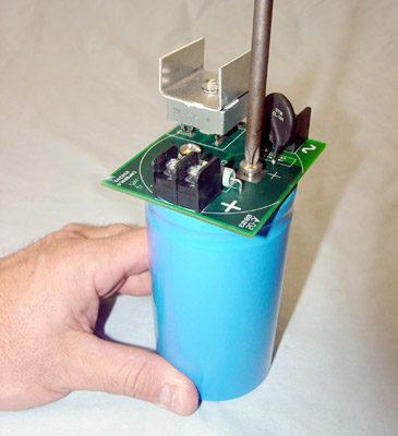
A capacitor is an electronic component that stores up
charge and will release it when called to.
Think of it as a reservoir for smoothing fluctuations in electrical
currents. Electrolytic capacitors
have particularly large capacities and are used in DC or linear power
supplies (See also Linear Power Supply) that are used in conjunction with
stepper and servo motors.

Carbide is an extremely tough compound (usually Tungsten Carbide or Titanium Carbide is the compound) used as a cutting surface in machine tools. It is valuable because it resists wear, heat, and is extremely rigid. The entire cutter may be made of carbide as in the case of a carbide end mill, boring bar, or twist drill, or a Carbide Insert (See Also Carbide Insert) may be used in indexable tooling (See Also Indexable Tooling) so that the cutting surfaces may be easily changed as they wear.
Carbide can and should typically be run at much higher
speeds and feeds than high speed steel.
An insert (See also Insert) made of carbide (See also
Carbide). These are the most commonly used type of insert.
Named for mathematician René Descartes, Cartesian coordinates provide a system for identifying the relative locations of points in space. Locations are specified by a set of numbers, with one number for each dimension (or axis if you are thinking CNC, See Also Axes). Each dimension is orthogonal to the others, meaning it is at right angles. Dimensions are usually lettered from X to Z for three dimensional. The number specifies how far from the Origin (See Also Origin) to travel along a particular dimension. The sign of the value determines which direction to travel from the origin.
The C-Axis is the rotational axis about the Z-Axis.
A center cutting end mill is one that has the ability
to cut with the center of it’s bottom face. This is crucial if you intend to plunge the
end mill, which is to send it straight down the way you would a drill
bit. Some end mills are not centercutting,
and the cannot plunge straight down as a result. Often, a larger non center cutting end mill
is not center cutting because there is a coolant passage down the core
of the tool that allows coolant to be injected directly into the cutting
action instead of coming from above.
Writing a CNC program where the toolpath is specified as the centerline of the mill cutter or the virtual tip in turning. The actual path is then generated from the centerline using tool offset and toolnose radius information. See Also Tool Offset and Toolnose Radius.
Chain drives are an option for moving the axis on gantry-style
machines such as routers and plasma cutters.
See
A chamfer is beveling applied to an edge so it will not
be sharp. This can be done for
reasons of appearance and feel, or to avoid weakness for stress. For two surfaces that meet at right angles,
imagine a chamfer at a 60 or 45 degree angles that just
takes the edge off for a very short distance.
Chamfering is a common machining operation, and it can also be
useful as a means of deburring sharp edges.
Chatter is a vibration or sound that comes from the machine
tool under certain conditions. It
interferes with proper cutting and produces cutting errors and bad surface
finish. Generally, it is a harmonic
vibration or natural resonance. It
can be triggered through improper setup or operation of the machine. Frequently, changing the spindle speed, depth
of cut, or feed rate can eliminate the chatter.
It is generally not advisable to continue cutting with chatter
present.
Chip augers and conveyers are features of machining centers
that are used to help manage the huge amount of chips and debris these
machines can produce in a short period of time.
They deliver the chips to a hopper that may then be used to cart
the chips off for disposal or recycling.
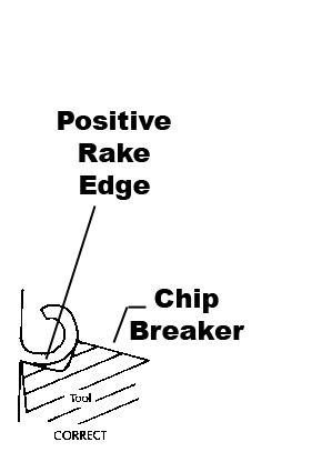
A chip breaker is a feature on a lathe tool or insert (See Also Carbide Insert) that is designed to cause the chip to break off by exerting force on it. The chip breaker causes the chip to curl until it breaks off.

Chipload a measure of the actual thickness of chip that is produced in the machining process. It is measured in thousandths (i.e.: 0.010) per tooth and may be influenced by the spindle speed, number of cutting edges on the tool, and the feedrate of a CNC machine. The number of cutting edges or flutes on a cutting tool determines how the chipload is divided. A single edge tool takes all the chipload during a revolution, while a multiple edge tool divides the load over multiple edges.
Chipload is an important factor in tool life because it dictates how much heat will be carried away from the cutting edge. Better heat dissipation directly relates to increased tool life. The formula for determining chipload is:
Chipload = feedrate / (rpm x #cutting edges)
A higher chipload will carry away more heat because the larger chips carry the heat away. To increase chipload, increase feedrate or decrease the rpm or number of cutting edges. All things considered, a 2 flute endmill offers a greater chipload than a 4 flute endmill running at the same spindle speed.
Note that higher chiploads will also result in a less fine finish, so a trade off is necessary. Machinery’s Handbook has tables of optimal chiploads. Just to give an idea, a chipload of 0.005” might make sense for roughing steel while 0.001” to 0.002” is better to finish.
A chuck is commonly a workholding device, although some types of collets, such as ER, are used primarily for toolholding and hence their collet chucks are also for toolholding. Chucks grip round objects almost exclusively, although they can grip square or hex objects, and a 4-jaw chuck with independent jaws has quite a range of shapes it can grip. Chucks are designed to rotate the workpiece or tool along an axis. They are most commonly used on lathes, on rotary tables, or on the mill, as a collet holder or drill chuck for twist drills.
A lathe without a tailstock.
G-Codes support three common types of motion:
- Rapids (G0): Moving
the tool as quickly as possible, preferably without cutting (although
the machine usually doesn’t enforce this) in order to get to the next
location where cutting is desired.
- Linear Interpolation (G01): Linear interpolation is smoothly moving multiple
axes of the machine so the tool follows a straight line as closely as
possible. Since the line is usually
not aligned with an exis, this requires motion
from more than one axis to “stair step” together to produce this diagonal
motion.
- Circular Interpolation (G02/G03): Circular interpolation
is smoothly moving multiple axes of the machine so that the tool follows
a circular arc as closely as possible.
Since the axes only move in straight lines, a series of tiny lines
are used to simulate an arc. G02
causes the motion to be in a clockwise direction, while G03 is counter-clockwise.
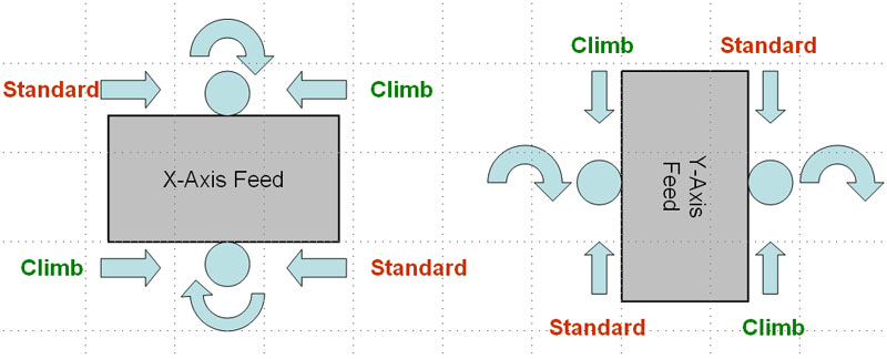
Depending on the direction of cut relative to the rotation of the cutter, a milling operation may be said to be either climb milling or conventional milling:

Note that in this illustration, it is the workpiece moving and not the spindle. If the spindle moves, the "Climb" and "Standard" labels would be reversed. Think of the spindle as a pinch roller that either helps the workpiece move faster in the direction its already moving (that's climb milling) or slows it down by turning "against" that motion.
It's called "climb" milling because it will tend to make the mill climb up the workpiece.
Some further thoughts on Conventional Milling (also called "Down Milling" or "Downhill Milling"):
Some further thoughts on Climb Milling (also called "Up Milling" or "Uphill Milling"):
There is a problem with climb milling, which is that it can get into trouble with backlash if cutter forces are great enough. The issue is that the table will tend to be pulled into the cutter when climb milling. If there is any backlash, this allows leeway for the pulling, in the amount of the backlash. If there is enough backlash, and the cutter is operating at capacity, this can lead to breakage and potentially injury due to flying shrapnel. For this reason, many shops simply prohibit climb milling at all on any manual machines that have backlash. Some machines even came equipped with a "backlash eliminator" whose primary purpose was to enable climb milling and its attendant advantages.
One way to think of it is to consider the concept of chip load. This is a measure of how much material each tooth of the endmill is trying to cut. Typical values for finish work would be 0.001 to 0.002" per tooth. For roughing work, that might increase to 0.005". Now in the worst case, climb milling may grab the table and slam the work into the cutter by the full amount of backlash during the instant when a single tooth is cutting. You can therefore add the backlash to the chip load to see what your new effective chip load might be in this worst case. Suppose you are roughing 0.005" per tooth and have 0.003" backlash. In the worst case, your chipload will soar to 0.008". That's probably not the end of the world, but it is a strain. Now suppose you have an older machine with 0.020" of backlash and are running an 0.005" chipload. If the worst happens there your chipload will soar to 0.025", which is probably going to break the endmill or something else.
The second thing to consider is whether cutting forces are strong enough to pull the table through the backlash in the first place. A lot will depend on the exact cutting scenario together with your machine. If you've got a fancy low friction linear way machine, it can grab easily. If you've got a lot of iron in the table, and maybe you're running with the gibs tightened a bit, it'll be harder. There are ways to calculate the cutter force, but in general, smaller end mills, less depth of cut, lower feeds, and lower spindle speed will all reduce the cutting force and make it less likely the cutter can drag the backlash out of your table and create a problem.
In general, the home machinist should investigate climb milling carefully
and responsibly. Don't run afoul of the backlash problems that can lead
to spectacular failure. Know what your backlash is, and therefore what
kind of chipload you can run before getting into trouble.
A clock spring cover is a springy spiral of material
that is wrapped around a leadscrew to protect it from chips and debris. It will contract and stretch to keep the screw
covered as the axis moves back and forth.
An alternative type of cover is a bellows (See also Bellows).
A motion control system in which there is feedback that
tells the controller whether the system was able to move in the desired
way after it was commanded to do so. In
CNC applications, a closed loop is typically created by using feedback
from optical encoders that measure how far a shaft has turned.
Close loop systems are often referred to as servo systems.
They are more complex than open loop systems, but they offer higher
performance and they are not subject to lost steps, which can greatly
improve their accuracy and reliability.
Another name for Constant Velocity Mode. G64 sets Constant Velocity Mode. Another way to view this mode is at the end of each move, the controller checks how far from the expected position it is and compares it to a coarse or fine boundary. G64 (Constant Velocity) uses a coarse boundary while G61 (Exact Stop) uses a fine boundary. See also Constant Velocity and Exact Stop.
Cogging is the tendency for a motor to have variable torque levels at different points in its rotation due to the internal configuration of the motor. Cogging is undersirable in a CNC drive motor, and sophisticated (and more expensive) motor designs try to minimize it. A good servo driver can significantly reduce the amount of cogging through encoder feedback.
Cogging is usually only a factor when one tries to use
a DC motor never intended to be a servo as a servo by coupling an encoder
to it. This is not to say it can’t
be done, just that performance will not be in the same class as a purpose-built
servo motor.
A collet is a device used to hold a tool or workpiece. There are many different collet standards including
5C (invented by Hardinge, commonly used with
lathes), ER, R-8 (the
A lot of machinists say that collets will give a better
surface finish than setscrew mill holders because they grip the endmill evenly all around the circumference.
A lathe with a tailstock. See also "Chucker". Also used to refer to a lathe that may be run as CNC or manual.
On lathes, Constant Surface Speed is the technique of varying the spindle speed as the tool approaches the axis of rotation so that the speed the cutter moves over the workpiece is constant. The speed must therefore increase as the cutter approaches the centerline.
The advantages of Constant Surface Speed are longer tool life, more consistent surface finish, and better cycle times. It also simplifies programming as the programmer can think in terms of surface speed rather than rpm.
The G96 code turns on CSS, while G97 turns it off. As such, G96 is a mode. It is desirable to cancel it as soon as possible
when finished cutting as it will slow things down if used during rapids.
This is the default operation for G-Codes, but is cancelled
by a G61, which causes the machine to enter “Exact Stop” mode (see Exact
Stop). In constant velocity mode
the machine does not pause between motion commands, but just keeps right
on going. Some lookahead (see
also Lookahead) processing may be done for optimal
results. This can result in some
rounding of corners, which is why Exact Stop mode is provided.
A contactor is a heavy duty relay capable of carrying
high currents such as those used by motors.
See also "Relay".
Movement in two or more axes at the
same time in order to produce a smooth continuous surface or curve.
Another term for Constant Velocity Mode (See Also Constant Velocity Mode). Constant Velocity Mode is better for contouring because it encourages a smooth interpolation between points making for a better surface finish.
A CNC lathe operation where a smooth continuous curve
is machined. It is analogous to
contouring on the mill, and may also be called “Profiling”.
Depending on the direction of cut relative to the rotation of the cutter, a milling operation may be said to be either climb milling or conventional milling:

It's called "climb" milling because it will tend to make the mill climb up the workpiece.
Some further thoughts on Conventional Milling (also called "Down Milling" or "Downhill Milling"):
Some further thoughts on Climb Milling (also called "Up Milling" or "Uphill Milling"):
There is a problem with climb milling, which is that it can get into trouble with backlash if cutter forces are great enough. The issue is that the table will tend to be pulled into the cutter when climb milling. If there is any backlash, this allows leeway for the pulling, in the amount of the backlash. If there is enough backlash, and the cutter is operating at capacity, this can lead to breakage and potentially injury due to flying shrapnel. For this reason, many shops simply prohibit climb milling at all on any manual machines that have backlash. Some machines even came equipped with a "backlash eliminator" whose primary purpose was to enable climb milling and its attendant advantages.
One way to think of it is to consider the concept of chip load. This is a measure of how much material each tooth of the endmill is trying to cut. Typical values for finish work would be 0.001 to 0.002" per tooth. For roughing work, that might increase to 0.005". Now in the worst case, climb milling may grab the table and slam the work into the cutter by the full amount of backlash during the instant when a single tooth is cutting. You can therefore add the backlash to the chip load to see what your new effective chip load might be in this worst case. Suppose you are roughing 0.005" per tooth and have 0.003" backlash. In the worst case, your chipload will soar to 0.008". That's probably not the end of the world, but it is a strain. Now suppose you have an older machine with 0.020" of backlash and are running an 0.005" chipload. If the worst happens there your chipload will soar to 0.025", which is probably going to break the endmill or something else.
The second thing to consider is whether cutting forces are strong enough to pull the table through the backlash in the first place. A lot will depend on the exact cutting scenario together with your machine. If you've got a fancy low friction linear way machine, it can grab easily. If you've got a lot of iron in the table, and maybe you're running with the gibs tightened a bit, it'll be harder. There are ways to calculate the cutter force, but in general, smaller end mills, less depth of cut, lower feeds, and lower spindle speed will all reduce the cutting force and make it less likely the cutter can drag the backlash out of your table and create a problem.
In general, the home machinist should investigate climb milling carefully
and responsibly. Don't run afoul of the backlash problems that can lead
to spectacular failure. Know what your backlash is, and therefore what
kind of chipload you can run before getting into trouble.
Conversational CNC is a method of using a CNC machine that does not require G-Code programming. Instead the operator interacts with a set of menus to define what the machine will do. The menus are often organized like Wizards around basic operations for the machine such as turning, threading, facing, boring, or grooving on a lathe.
Conversational CNC is very convenient on machines that
are used for one off jobs because they save the time of programming on
simple jobs.
Try our G-Wizard CNC Conversational Programming software to learn more.
Liquid, air, or mist injected at the workpiece and cutting
tool in order to evacuate chips, provide cooling, and provide lubrication. Proper use of coolant can prolong tool life,
allow higher cutting speeds, and improve surface finishes.
A G-Code, G68, enables coordinate system rotation for milling machines and G69 cancels it. It can be advantageous to rotate the coordinate system in a variety of situations. For example, perhaps the work is rotated slightly and is not square to the X, Y axes. It may be easy to simply measure the angle it is off by and rotate the coordinate system to compensate before starting the part program.
For many controllers, coordinate system rotation is an additional cost option.
An axis letter followed by a numerical value signifying a coordinate value. For example, X24.7500 is a coordinate word in the G-Code language.
Counterboring is a common machining operation. It is often used to recess a bolt head down into the hole. The are counterbore cutters specifically made for the task, or some folks plunge cut with endmills. The endmill will not leave quite as flat a hole as a true counterbore, but it is often good enough.
A counterweight is often used to offset the weight of
a vertical axis to provide for smoother operation. Counterweights can literally be constructed
of weights, sometimes supported with compound leverage to reduce the weight
required, or from other mechanisms such as gas springs.
The unhappy case where the machine makes unintended contact of some kind, perhaps with the workholding components. Always run a new part program with offsets (See Also Offsets) set to "cut air", in other words cut above the workpiece and any workholding, and do so slowly. You can use the feedrate override (See Also Feed Rate Override) to slow things down, as well as using Single Block mode (See Also Single Block) to manually control execution. Functions like Toolpath Simulation (See Also Toolpath Simulation) and Soft Limits (See Also Soft Limits ) are an aid to testing out part programs and controlling their ability to do damage.
Another source of crashes can sometimes occur in closed loop systems (See Also Closed Loop) if the encoder loses its connection. In this case, an axis can suddenly accelarate to maximum speed in an effort to "catch up" to an encoder that has quit responding. The results are often a spectacular crash.
The predetermined distance from the
surface of the workpiece where the cutter can be moved rapidly between
cutting operations. See
also R-Level.
An offset used to compensate for differences in tool
diameter.
The force exerted by the tool on the workpiece, and in
an equal and opposite reaction, on the machine itself. High cutting forces can potentially cause deflection,
which can lead to inaccuracy and chatter. Ultimately, it can even break the cutter.
The control on the panel that begins
program execution, or resumes execution of a program that has been paused.
The control on the panel that halts
program execution.
| CAD to Cycle Stop |
|
Do you want to be a better CNC'er in 37 Seconds? Get Better Tool Life, Surface Finish, and Material Removal Rates Fast. It's that easy. You can install and get results now.
|
||||||||||||||||||
| ||||||||||||||||||