|
Do you want to be a better CNC'er in 37 Seconds? Get Better Tool Life, Surface Finish, and Material Removal Rates Fast. It's that easy. You can install and get results now. |
| Datum to Following Error |
Datums are imaginary geometric shapes, such as a point, line, plane, circle, or cylinder. A datum feature is a physical feature of the workpiece or part that acts as a physical analog to the datum and is a point of reference or a point where measurements are made.
There is a particular datum called Part Zero
Deflection is unintended bending of a tool, workpiece,
or machine component. It leads
to inaccuracy or perhaps worse if it causes damage to the tool, workpiece,
or machine. Rigidity is the counter
to deflection.
This is the torque you feel when you twist a stepper
motor that has no power applied to it.
The detent torque can cause a stepper motor to try to hold its
position even when power is switched off, at least to the nearest step. With no power, the microstep
position will be lost.
Digital Differential Analyer, abbreviated "DDA" referred to a mathematical technique or algorithm used to interpolate paths for motion control, computer graphics, and other applications. In CNC applications, interpolation is necessary because the axes of the machine move strictly at right angles to one another. Any motion not precisely aligned with the axis is always an approximation of a true smooth motion. The approximation is done by moving more than one axis at a time, by a relationship calculated by the DDA algorithm.
The DDA algorithm is loosely based on the differential equation of the line to be interpolated, which is:
dy / dx = constant
It operates by doing repeated addition of 2 values (dx and dy) to the x and y position of the last point to derive the next point on the line.
Some servo and motion control systems allow the user to examine the DDA values for debugging purposes.
A mechanism for mapping the 3D surface
of a real object and producing a computer model suitable for a CAD/CAM
program from the model. Digitizing
can be accomplished using a Tool Probe (See Also Tool Probe) or Laser
Scanner to name just two relevant technologies.
Distributed Numeric Control is a protocol, similar to
a local area network, used to link together CNC machines on the shop floor.
Before DNC, it was necessary to deliver part programs to the machine
using other means—originally paper tape, later floppy disks or bubble
memory, and lately using USB keys.
Depth of cut is a measurement of how much material the cutter is removing along one axis. So, a ½” endmill whose end is 0.020” into the surface of the material being cut, either below the face in the Z-direction or along the sides of a slot or pocket in the X or Y directions, has a 0.020” depth of cut.
Obviously it takes more power to run a higher depth of cut. You may need to run at a slower feed rate or spindle speed if you run a greater depth of cut. For CNC machines, it can be more advantageous to reduce the depth of cut, increase spindle and feed rates, and just make more passes to reach the desired depth.
Depth of cut is typically less than the diameter of the
cutter, and sometimes much less depending on the rigidity of the machine
and cutter.
Dongles, also called USB Keys, are electronic keys that are used to copy protect software such as CAD or CAM software. The software will not operate unless the dongle is in place on the machine trying to run the software.
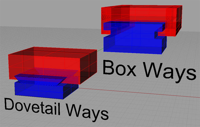
Sliding ways are used by many machine tools so that their
axes may slide against one another. There
are four prominent designs:
-
Dovetail Ways: Very
common on mills, dovetail ways look like the dovetails used in wood joinery.
-
Box Ways: Box Ways
are rectangular cross section, as opposed to the angular shape of dovetail
ways. Box ways are very strong,
but they suffer from two shortcomings.
First, they involve a lot of surface contact area, so managing
friction is key. Second, in order
to slide at all, some clearance is required, which results in some slop
in their travel. They are the strongest
and most rigid design, but they are difficult and expensive to manufacture.
-
-

Drawbars are used to pull collets and toolholders
into their tapers. See Also Taper. They may be threaded into the collet, or they
may grip the toolholder’s Retention Stud.
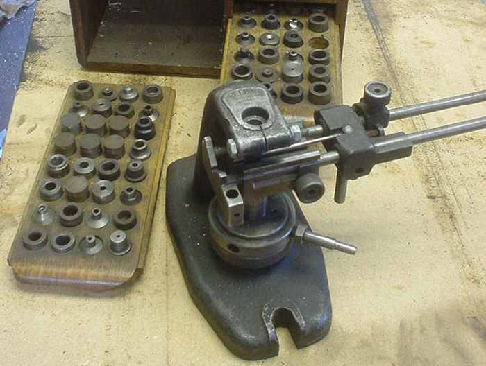
A drill bushing is a hardened steel cyclider with a hole
in it the diameter of the drill bit. They're designed to support the end
of the bit to increase the precision when drilling. Drill bushings may
be inserted into a jig.

Drill drift is the tendency for a twist drill to wander when just getting started, or to wander due to conditions in the hole. To reduce drill drift and ensure a more precise hole, use a spot drill before drilling the hole and/or use a drill bushing. See also "Drill Bushing" and "Spot Drill".
Drip feeding is a technique of feeding the part program
to the CNC machine a little bit at a time if the whole program is too
large to fit into memory at once.
An electronic circuit used to control the current sent
from the power supply to a motor and thereby control what the motor does. A Gecko drive is one example of a driver.
A Digital Read Out or DRO provides a digital indication
of the position of one or more axes on the machine. DRO’s typically use
linear scales (See Also Linear Scales) to measure the position, but other
technologies have been used as well.
In Mach3, a DRO is a numerical indicator within the program
that has a number of different capabilities and properties.
Dry machining is the process of machining without coolant. Often a strong stream of compressed air is used to cool chips. Dry machining can often increase productivity and reduce chip breakage at very high SFM rates. It is also used in some cases because it is less messy or healthier for the machinists.
On the other hand, unless properly applied, it can seriously
reduce the life of your tooling. Be
sure to check carefully with your tooling supplier about dry machining
parameters.
Refers to using two angular contact
bearings (See Also Angular Contact Bearing) in pairs. The bearings are usually a matched pair and
should not be separated. They’re
matched by being ground to match one another, and when used in proper
combination, this provides a preload (See Also Preload).
An intentional delay to keep a rotating
tool in contact with a part, perhaps to improve finish. G04 is the G-Code command to force a dwell between
operations.
An AutoCad CAD file format.
DXF is the Autodesk file format and file extension for
Autodesk CAD drawings. It’s also
a common format that most CAD and CNC-related programs can read and write.
A device used to find the exact edge of the workpiece
along the x or y axis. Edge finders
can rely on electrical contact, a sensitive pressure switch, or be strictly
mechanical.
An encoder is an electro-mechanical device used to measure
shaft rotation. Often they are
optical in nature. They’re
used to provide feedback in closed loop control systems. Encoders are often associated with servos.
End mills are cutters used in milling machines. They superficially resemble drill bits, although
it is very superficial. There are
a number of characteristics involved in selecting the best endmill for the job including:
- Number of flutes.
Endmills may be had in a variety of configurations
including 2, 3, 4, or more flutes.
- Roughing or
Finish Style: Roughing endmills
are good for hogging out material, but not so great for finishing.
- Centercutting:
Determines whether the endmills center cuts. If not, the mill cannot be used to plunge cut.
See Also Centercutting.
- Material: Endmills are made from a variety of materials ranging from High Speed Steel to Solid Carbide.
- Coating: There are a variety of coatings designed to improve the performance of the endmill.
- Type: Standard, ball nose, double ended, etc.
- Length: Shorter endmills are more rigid (See also Rigidity), longer endmills may be needed to reach.
- Diameter
There are many other characteristics that define an endmill.
The control that stops all machine
operation. Usually it physically
interrupts all power to the spindle and axis drive motors. Once an e-stop has been triggered, a special
operation is normally required to resume power.
G-Code G09 performs an Exact Stop Check. The Exact Stop Check command is similar to Exact Stop Mode (See Also Exact Stop Mode), except that it only takes effect on the next change of direction and then is cancelled, so it only works once, rather than continuously like the mode.
Triggered by G61, and cancelled with G64 (see Constant
Velocity Mode), Exact Stop mode causes the machine to bring the axes to
a full stop between each motion command.
This can result in less rounded outside corners.
The downside is that if the tool comes to a full stop it will have
a tendency to leave witness marks on the workpiece there.
Face milling is the act of milling a surface perpendicular
to the axis of rotation of the cutter.
A face mill is a cutter specifically designed for this purpose.
A part program word that determines feed during program
execution.
The act of moving the workpiece relative
to the cutter. Either or
both can move. See also Feedrate.
A CNC machine panel control that stops
the machine from executing further commands.
A control on the panel that allows
the operator to manually increase or decrease the federate. This allows the operator to fine tune the program
without the need to rewrite any g-codes. Feedrate override is a percentage of the programmed
value.
In control systems, a feedback loop is one where a sensor
provides feedback to help control a motor or other device. In CNC, closed loop (See Also Closed Loop) systems
incorporate feedback to increase accuracy and performance.
The rate at which the cutting tool
and workpiece move in relation to one another. Faster feed rates can remove material more quickly,
but may require more power or may wear out the cutter sooner.
Refers to the feedrate and spindle speed that should
be used for an operation or that a machine is capable of using. Machinery’s Handbook has comprehensive information
on what the best feeds and speeds are.
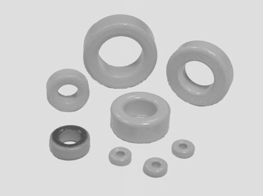
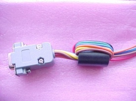
Ferrite beads are used to reduce noise in electrical systems. Pop a bead onto each power line--AC to power supplies, DC to each motor driver, +5V logic supply, etc. The beads eat the noise by resisting the flow of high frequencies onto the line. Because they cut out high frequency noise, they're ideal for AC and DC power lines, which are operating at no frequency (DC) or low 60 Hz frequency (most AC).
They come in two forms:

Raw ferrite beads: thead the wire through them:

Wire threaded through a ferrite bead...

Clamp-on ferrite: ideal for power cords and adding after the fact...
Another name for Exact Stop Mode. G61 sets Exact Stop Mode. Another way to view this mode is at the end of each move, the controller checks how far from the expected position it is and compares it to a coarse or fine boundary. G64 (Constant Velocity) uses a coarse boundary while G61 (Exact Stop) uses a fine boundary. See also Constant Velocity and Exact Stop.
A final pass with very shallow depth of cut (See Also
DOC) that provides higher accuracy and better surface finish than a roughing
cut.
Generically jigs and fixtures are used to guide and hold
the workpiece. A jig may also guide
the tool, while a fixture does not.
Using a very high volume of coolant (See Also Coolant)
to ensure good chip evacuation and cooling.
Use of flood coolant requires a reservoir, pump, delivery piping,
and some form of enclosure so that the coolant doesn’t spray everywhere.
The term “flute” refers to a cutting surface. A 4-flute endmill (See Also Endmill) has 4 cutting
surfaces.
A type of cutter that is a single point cutter (See Also Single Point Cutter) meaning there is only one cutting edge. Flycutters are commonly used in milling operations. The can produce a good surface finish over a broad area. They make a characteristic thumping noise due to the fact that they are basically taking an interrupted cut. Fly cutters come in many varieties ranging from specialized cutters (perhaps used to make a gear) to more general versions that use lathe tools.
A typical R-8 shank fly cutter with a brazed carbide lathe cutter installed...
In a closed loop system (See Also Closed Loop), following
error is the difference between where the axis is based on feedback (See
Also Feedback) from an encoder (See Also Encoder) or other device, and
where it should be, based on what the CNC control program has commanded.
Closed loop systems will have a maximum following error that they will permit, beyond which they fault the servo and stop the machining process. So long as the following error does not exceed the maximum, the axis may eventually catch up again and eliminate the error.
Given real world limitations, it isn’t practical to insist
on 0 following error at all times.
In follow turning two tools and two independent tool turrets are used on a CNC lathe to speed cutting. Each tool cuts at the desired depth of cut, with the second tool starting its cut where the first left off. In this way, twice as much material can be removed per pass.
| Datum to Following Error |
|
Do you want to be a better CNC'er in 37 Seconds? Get Better Tool Life, Surface Finish, and Material Removal Rates Fast. It's that easy. You can install and get results now.
|
||||||||||||||||||
| ||||||||||||||||||