|
Do you want to be a better CNC'er in 37 Seconds? Get Better Tool Life, Surface Finish, and Material Removal Rates Fast. It's that easy. You can install and get results now. |
| G12/G13 to Knee Mill |
G12 and G13 are G-Codes (see also G-Codes) in the part program that specify a circular pocket be milled. G12 causes the pocket to be milled in a clockwise direction while G13 mills counterclockwise. The radius of the circle is typically specified with an "I" command. For example "G12I5" specifies a pocket with a radius of 5 be cut in the clockwise direction. The cutter should be positioned to the center of the circular pocket using a move in a prior block or an X and Y command in the same block. The tool will return to center when the pocket is finished.
Clockwise and counterclockwise variants are provided so that the user may select climb versus conventional (see also Climb Milling and Conventional Milling). For example, with clockwise spindle rotation, G12 (clockwise) results in conventional milling.
Note that with a suitable cutter, such as a woodruff key cutter (see also Woodruff Cutter), it is possible to use G12/G13 to cut grooves or slots in the pocket wall.
Circular pocket milling is how CNC'ers cut holes larger than their cutter. It is sometimes called spiral interpolation and sometimes helical interpolation. True helical interpolation involves a helix, while spiral interpolation keeps the entire cut in the same plane.
A type of tooling arrangement on lathes where multiple
cutters are mounted on the cross slide which is repositioned to allow
each tool to access the part. For
example, it is common to mount the cutoff tool behind the part (and usually
upside down unless the spindle is reversed when the rear tool is in use).
Gang tooling provides a simple way to employ multiple
tools when a turret is not available.

A gantry mill uses a bridge-like arrangement to support
the Z-Axis, which travels across the bridge for Y-Axis motion. They are very common for router and plasma applications,
and somewhat less so except for large configurations when milling steel.
Similar to a gas strut, a gas spring may be used as a
counterweight (See Also Counterweight) on a Z-Axis to improve performance.
The generic slang term for the program
that controls a CNC machine. The
more proper term would be “Part Program” (see also).
Literally, a G-Code is the type of word in those programs
that determines the type of operation the machine will do next.
Try the CNCCookbook G-Code Reference for a sampling of g-codes. We also offer an Online G-Code Tutorial.
Here are some online references describing g-code:
The Light Machines Manual has some excellent g-code documentation.
Mitsubishi Controls G-Code Documentation.
Peter Schmid's excellent, "CNC programming handbook" is the reference many classrooms use.
Then there are some unique sources, such as this PowerPoint slide show describing some of the G-codes that are special to Haas mills.
Gear drives may be used to drive spindles or drive motors.
They’re less common for drive motors because they typically involve
backlash (See Also Backlash) unless very carefully designed.
They’re convenient for spindles because a transmission can usually
be incorporated that allows several speed ranges.
A manufacturer of drive motor controllers
or drivers or drivers for stepper motors and servos. Gecko also makes the G-Rex.
GD&T is a comprehensive set of
conventions for efficiently and accurately communicating geometry requirements
for features on components and assemblies. The appropriate standard defining
GD&T is ASME Y14.5M - 1994.
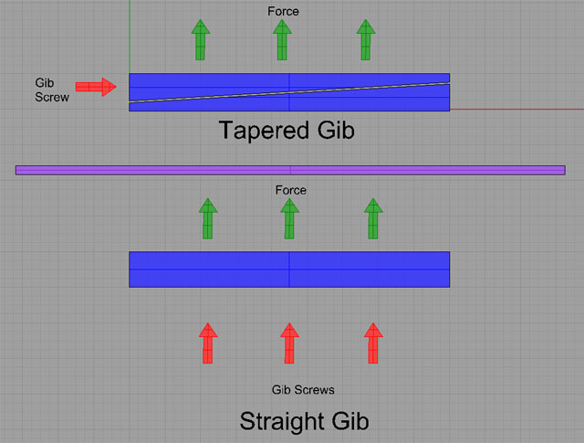
Gibs, usually pronounced with a hard “G” sound, are pieces
that fit in ways (

This is a collection of notes on how to adjust your machine's gibs that I've found all over the web. I've tried some, other's have tried them, and people tell me they work. Before talking about their adjustment, and assuming we're not talking about gibs meant to be locked and unlocked all the time, be sure you have some sort of locking mechanism so that you can maintain that adjustment despite machine vibration. My lathe has a jam nut that holds the gib adjustment, for example. Products like Loctite should also be considered.
The first question is, "How would I know whether I need to adjust my gibs?" Unfortunately, the best answer I have here is you won't know if you don't try. Be careful not to tighten them too much or you'll really lock down the axis and generally make things worse. For some kinds of cutting you may find it advantageous to lock an axis in this way. I have seen the practice recommended, but the one time I tried it on my lathe the result was no improvement and a badly adjusted gib so I steer clear unless the machine comes with tapered gibs (See Also Tapered Gibs) and locking handles.
Some folks limit gib adjustment entirely to a degree of tightness for the slide. They back off all screws and start on the centers, tightening just enough to create a slight drag on the slide when there are no leadscrews attached. A similar approach involves tightening that center screw until it is "just snug" and then following up with the ends. The latter is an approach I used with some success on my Lathemaster lathe.
I have seen one source that recommends lapping the gibs, as they are often of somewhat poor or rough finish. CNC machines make gib adjustment a little more difficult.
Without handwheels, you can't really feel how tight they are. Commercial CNC machines make the adjustment by measurement how much amperage is drawn by the motor during traversal. One account I read indicated the gibs should be adjusted until they are about 30% to 50% of the maximum rated amperage for the motor on the same axis as the gib.
An approach that is more analytical can be used for both manual and CNC machines. This is supposedly the factory procedure used by Bridgeport to set them. Use a 0.0001 reading indicator and measure the slop in the slide. Example: For the X axis, place the mag base on the end of the saddle and put the stylus on the table. At that end of the table push and release. Then pull and release. The differance is the amount of clearance in the slide. Repeat at the other end of the saddle. Adjust gib in a like new machine with little wear to give a reading of 0.0005. A machine with more wear will have to be checked with the table closer to the end of travel. The same procedure is used to set the saddle to knee gib. There must be some clearance for the oil film and that film also helps dampen vibration. On a machine with hardened and ground box ways and turcite on the moving member the procedure is to set the clearance to almost nil. 0.0001 is a good number.
Another approach was based on trying to minimize backlash
by making the gibs as tight as possible. In this case, it was advocated
to overtighten the gibs until backlash due to flexure against a locked
table was measurable, and then gradually back off in ¼ turn increments
until that backlash was minimized.
The G-Rex is sort of a super breakout board (See Also
Breakout Board) that uses a LAN or USB connection back to the computer. It provides a large number of inputs and outputs
as well as control of up to 6 axes. The
G-Rex incorporates a dedicated microprocessor to run the innermost motion
control loops. This tremendously
lightens the load on the PC running the CNC control software and allows
for much higher performance.
Handwheels are used to manually operate the axis of a
CNC machine. They are generally
connected to an electronic device called an MPG (See Also MPG) that sends
signals through the CNC controller to the drive motors rather than directly
moving the machinery via a leadscrew.
Hardness is a material's resistance to plastic deformation and scratching. It is a measure of how difficult it is for the cutting tool to cut the material. Knowing the hardness of a material is helpful in deciding how to go about machining it, particularly for materials like steel where there are many different alloys and heat treatments (See Also Heat Treatment) that lead to a wide range of hardnesses.
There are a variety of scales used to measure hardness, including Rockwell, Brinell, Vickers, and Knoop. Testers are also available that can determine the hardness of a material in various ways. If you know what allow you are using, Machinery's Handbook and other reference sources will have hardness information.
A harmonic drive is a gear drive of novel design that
offers minimal backlash. As such
they are ideal reduction drives to go between stepper or servo motors
and the machine axis.
Heat Treatment is the process of using heat in very controlled ways to change the properties of a material. For example, heat treatment may be used to harden certain alloys of steel.
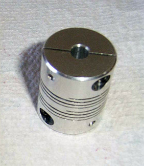
A type of shaft coupler that has a helical slot cut through
the middle. This allows the coupler
to flex which enables coupling of shafts that are not quite true to one
another. Helical Beam Couplers
are a popular way to couple stepper and servo shafts to the reduction
drive.

A coordinated motion in x, y, and z axes that causes the tool to follow a helix. Helical interpolation is useful for a variety of operations, including ramping and thread milling. See also "Ramping" and "Thread Milling".
The helix angle is a characteristic of an endmill that is the angle from the vertical of the helical flutes. The most common helix angle is 30 degrees because it offers the broadest range of usability. Increased machine rigidity and solid carbide endmills argue that a 45 degree helix angle may be a better choice. The greater the angle, the faster the helix.
Using smaller cutters at much faster spindle speeds and feed rates to make many lighter cuts that take the place of deeper slower cuts with larger cutters in conventional machining.
If the speed is high enough, and the chips are evacuated well enough due to the high speeds and perhaps an air jet, coolant may not be necessary or may even be detrimental as the chips carry away most of the heat. Higher feed rates really facilitate this.
The advantages of HSM include higher accuracy, faster cycle times, and more accurate parts. Cutting forces are diminished in HSM, which can even result in greater tool life. Positive rake tooling also reduces cutting forces, and is desirable for HSM.
HSM requires the ability for the CNC machine axes to accelerate, decelerate, and move very quickly in order to make up for the time lost in making much lighter cuts.
The easiest way
High Speed Steel, abbreviated HSS, refers to steel used to make cutters. It is called "high speed" because it is an alloy designed to withstand the heat of cutting better than milder steels. In the pantheon of cutter materials, HSS is one of the more common and plebian varieties. Carbide (See Also Carbide) is harder, more rigid, and withstands higher temperatures, although it is also more costly and more brittle on the downside.
The maximum torque that can be applied
to an energized but stopped motor (especially a stepper motor) without
moving it.
A position sensor that is used to establish a reference position for an axis. There is typically one per axis. On many CNC machines, one of the two limit switches serves double duty as a home switch. When the machine is commanded to home, it simply moves in the defined direction until the limit switch is triggered.
See also “Limit Switch”
A machining center (
A hybrid stepper motor is a DC brushless permanent magnet
motor with a wound stator. It is
designed to move discrete increments or steps by sequencing the current
to the windings.
A driver feature that reduces current
to the motor when it is not turning in order to reduce heating and conserve
power.
A vendor independent standard for exchanging
CAD information or files. A
CAD program file format.
A measure of feedrate. See Also Feedrate.
The distance covered (feed rate) as each tooth engages
the workpiece. A
measurement of Chip Load.
A pulse usually associated with spindle indexing that
determines when a point on a rotating shaft has been passed. See also Spindle Indexing.
Indexable tooling uses carbide inserts (See Also Carbide
Insert) as the cutting edges. When
the insert dulls or chips, it can easily be replaced with a new one for
a fraction of the cost of replacing the whole tool.
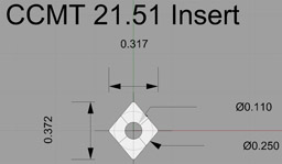
An easily changeable cutting surface
that may be used with indexable tooling (See
Also Indexable Tooling).
Inserts are generally very cheap compared to the cost of replacing
the entire cutting tool, and so provide an economical way to use carbide
(See Also Carbide or Carbide Insert) for high performance cutting in machine
tools.

A type of indexable tooling that uses a carbide insert to bore a hole. Each drill is designed for a specific size hole. Often, insert drills will have coolant passages to allow coolant to be pumped through the drill and down to the very bottom of the hole.
Generically jigs and fixtures are used to guide and hold
the workpiece. A jig may also guide
the tool, while a fixture does not.
Jogging is the operation of manually causing an axis
to move under power. It is often
convenient to jog using a handheld pendant control (See Also Pendant). A mechanism is usually provided to control the
speed of jogging.
A keyboard emulator is an electronic circuit that accepts
a number of inputs and converts them to keystrokes which are fed into
the PC’s keyboard input. This is
a convenient way to add additional control panel inputs on systems that
use a parallel breakout board (See Also Breakout Board) because it conserves
scarce input lines on the parallel port.
IPAC is one example of a keyboard emulator board.
Knee mills support the table, X, and Y axes on a knee
and raise the table up and down whereas a bed mill (See Also Bed Mill)
moves the spindle up and down. The
| Gang Tooling to Knee Mill |
|
Do you want to be a better CNC'er in 37 Seconds? Get Better Tool Life, Surface Finish, and Material Removal Rates Fast. It's that easy. You can install and get results now.
|
||||||||||||||||||
| ||||||||||||||||||