|
Do you want to be a better CNC'er in 37 Seconds? Get Better Tool Life, Surface Finish, and Material Removal Rates Fast. It's that easy. You can install and get results now. |
| Tangential Control to Workshift Offset |
A Mach 3 feature that lets the A-axis rotate so that
a knife or other cutter is kept aligned with the direction of travel.
There are many tapers
associated with CNC including ISO, BT, CAT, R-8, Morse, Jacobs, SK,
and HSK. Unlike almost all other tapers, R-8 and Morse
can refer to both a collet and a toolholder
shank.
Most commercial CNC machines in the
HSK holders are a more recent attempt to improve on the CAT taper, and they are gaining slow acceptance.
The R-8 taper was introduced on the
There are a number of links with specs for Machine Tapers on our Reference Sources page.
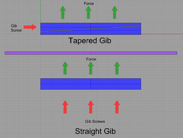
There are two types of gibs, straight gibs and tapered gibs. Straight gibs are adjusted by screws spaced out along the length of the gib. The screws push the gib in to create more contact with the sliding mechanisms. Tapered gibs use one or two screws. The screws are located in each end of the tapered gib. One screw acts as an adjustment while the other screw acts as a locking mechanism. Because tapered gibs are wider on one end than the other, they slide in or out creating more or less contact between the sliding mechanisms.

Tapered gibs are simpler to adjust because you don't have to try to balance out the force on all the screws as you would with straight gibs, and they often provide better contact and more uniform wear. Higher end machines generally use tapered gibs in preference to straight gibs, although not exclusively.
See also Gibs and Gib Adjustment.
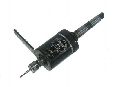
A tapping head is a device that goes into a machine spindle (could be a mill or a drill press) for the purpose of matching the spindles speed with the motion that is ideal for tapping. Tapping heads have clutches, gears, and may have reversing mechanisms. If equipped with a reversing mechanism, the head will reverse the direction of rotation when pressure is released so that the tap may be withdrawn. Use of a tapping speed provides a quick and efficient means of driving a tap into the workpiece.

A Tapping Head...
A word that selects a specific tool
in a part program.
Thread milling is a method for producing a thread on a milling machine. To cut a thread using a mill, helical interpolation (see also "Helical Interpolation") is used to describe the helical motion of the threads. A single point cutter is used to cut one or more threads.
A lot of useful information on thread milling is available in the Vardex Thread Milling Handbook.
A toothed or ribbed belt where the
teeth run all the way across the width of the belt. The corresponding pulley has grooves that fit
the teeth on the belt. This is
a common and very successful mechanism by which a drive motor may be
connected to a leadscrew. This
is typically done to move the motor to a more convenient location or
to allow there to be a ratio between the motor’s rotation and that of
the leadscrew.
A workholding apparatus that stands
up high like its namesake and is used to attach parts to its vertical
sides.
A device that allows a
The amount of circumference of the
cutter, measured in degrees, that is involved in cutting at a particular
point in the toolpath.
An offset used to account for variations in tool length.
It can be advantageous to set up all the tooling so that the
same offset may be used for all tools, eliminating confusion about whether
the proper tool length offset has been set up for a particular tool.
The tool nose radius represents the radius on the nose
or cutting edge of a single point tool for a lathe. Compensation for tool nose radius is an offset
to ensure the proper cut takes place based on the tool nose radius of
the tool in use.
The
toolpath is the series of coordinate positions that determine the movement
of a tool during a machining operation, or literally the path the tool
follows as the CNC machine guides it through the work. Toolpaths may
be manually generated by the programmer or automatically generated by
a CAM program using an appropriate Toolpath
Strategy as specified by the programmer. See also CAM.
An animation display that shows what the toolpath will
be to produce the part. Toolpath
simulations are useful debugging and informational tools for the development
of part programs.
A tool table is a feature in CNC controller software
such as Mach 3 that provides a list of tools along with information
and parameters on how the tools are to be used.
A device whereby the tool is advanced until it triggers
the pre-setter to determine where the tip of the tool is and thereby
set the appropriate offset. Pre-setters
are basically switches mounted out of the way but within reach, perhaps
near the limit of travels.
There are some clever ways to create a pre-setter,
for example, by completing an electrical circuit, perhaps between the
toolholder and the chuck or vise holding the workpiece.
Pre-setters eliminate the need for the operator to
measure tool offsets and enter them into the system.
They are also often used to check whether a tool was broken during
an earlier operation so that the machine can be stopped and the operator
can replace the broken tool.
Toolsetters are devices used to precisely set the overall height of a tool when in its toolholder. CNC machines need to know how far the tool sticks out with precision and these machines help make that measurement consistent.
An alternative is a tool pre-setter, which measures
the tool length on the machine. The
advantage of a toolsetter is the tools can
all be set up in the holders ahead of time, which may save time on the
machine.
A Torch Height Control or THC is used in plasma cutting
applications to maintain a constant height over the work. This enables the torch to track surface irregularities
and warpage that can occur during the cutting.
A toroidal transformer is
a transformer wound on a round toroidal core. See also Transformer. They are favored over rectangular transformers
because they are somewhat more efficient.
Torque is a measure of the angular force needed to
produce rotation.
To determine the exact location of a feature or tool’s
tip by touching the tool to the feature or a known location. A sensor may be used, or often, a piece of paper
of known thickness is placed between the tool and the feature and the
tool is slowly advanced until the paper is just trapped between the
two. Advance too quickly and the tool or feature
can be chipped.
A touch probe is a sensitive device that can tell with
a very high degree of precision when the probe touches another object
such as the workpiece, vise, or part of the machine.
They typically have a small tip with a ruby or sapphire. They have a variety of applications such as
digitizing.
Tramming a mill is the process
of adjusting a moveable head until it is square with the table. See also Squaring.
Tramming a vise is the process
of adjusting the vise until the jaws are square with the desired axis.
Tramming is normally performed
with the aid of a dial test indicator or dial indicator and some sort
of holder such as an Indicol to attach the
indicator to the spindle.
A transformer
is an elecronic component used to transform voltages. Depending on how many windings are on the primaries
and secondaries, voltages may be increased or decreased. Transformers are a common component in power
supplies, and may be either conventional rectangular designs or round
toroidal designs.
The distance
a particular axis can move is referred to as its travels.
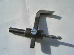
A type of
boring that involves cutting only a ring and removing a solid plug of
material from the hole.

A trepanning tool...
The science of friction, lubrication, and wear when two contacting surfaces are in motion relative to one another. http://www.tribology-abc.com/ contains a lot of useful reference information on Tribology.
T-Lathes are intended to spend all of their time facing. Most do not have a power feed in Z.
T-Slots
are a common mechanism for attaching vises, rotary tables, and clamps
to the table of a machine tool. They
resemble an inverted T. A nut
of the same shape slides into the T-Slot and studs are threaded into
the nut from above.
A
The number of turns required to advance a leadscrew
one inch.
The component of a lathe that holds
a number of cutting tools. Analagous to a
toolchanger on a mill.
Twisted pairs are a wiring technique
used to increase noise immunity (See Also Noise). The idea is to twist
a signal wire around it's corresponding ground wire. A noise spike will
affect both wires equally, and so the ground potential will rise along
with the signal. Since most circuits only consider the difference between
the two, the noise will be ignored. CAT5 LAN wiring is a typical twisted
pair system that uses 4 twisted pairs or 8 conductors. If the corresponding
grounds are not paired with their signals, there is little noise immunity
provided by a twisted pair approach. The twisted pair approach is commonly
called a Balanced Circuit.
An undercut on a mill is when the cutter has to reach
under a shelf, so that the cutter is working on a surface not visible
directly from above. Obviously
the cutter must stick out from the shank in some way and there must
be clearance to get the cutter into position under the shelf.
Step motors are typically 4, 6, or 8 wire devices.
Bipolars have no center taps, so if there are only 4 connections, the
motor is a bipolar only design.
Universal Serial Bus. This standard has largely replaced the old parallel
port standard as a way for PC’s to communicate with other devices as
well as the older RS232 serial standard (See Also RS232). Unfortunately, most CNC software and breakout
board capabilities have not kept up with some notable exceptions such
as ModIO (See Also ModIO).
A
VFDs or "Variable Frequency Drives" are great gadgets that go between the power source and a motor and allow the motor's speed to be continuously varied. They do this by means of something called "Pulse Width Modulation" where they are essentially varying the frequency of the current going to the motor. Thing of the frequency as governing how many "pushes" the motor gets. 60 Hz or 60 cycles per second is normal. A typical Hitachi 3HP VFD can deliver 0.5 to 360 Hz, which is quite a speed range!
Enter a new and better gadget, which has the really sexy name "Vector Drive." A white paper by Reliance Electric gives the full details, but in a nutshell, these drives are called vector drives because they understand the vector relationship between magnetizing current and torque producing current and they do the right thing with that.
What does doing the "right thing" buy us? Well, several things are better for vector drives than plain old VFD's:
Are we beginning to see why modern CNC machines like vector drives for spindles?
What's the downside? Largely cost. An equivalent vector drive probably costs 20 to 30% more than a VFD of the same horsepower capacity and it will require you to install a tachometer input to give it feedback on what the spindle is doing.
A
A
A device used to vary the speed of an AC motor by varying
the frequency of the electrical current sent to the motor. They are a very effective way to control spindle
speeds in that respect. Many
models have an input that allows the CNC control program to vary spindle
speed as needed.
A small power supply that is attached
to the plug and sits directly on the wall outlet. They have very low current capability but are
useful to power breakout boards and other logic that does not require
much current.
Way covers are used to protect the ways and leadscrews
from chips, coolant, and debris produced during machining operations. They reduce wear and preserve accuracy. See also Bellows and Clock Spring Covers.
An offset that allows for the slight
adjustment of tool tip location to account for part deflection, tool
wear, etc.
Whipping is the tendency for leadscrews or other long
objects to whip back and forth when rotated while unsupported at one
end or when too long and thin for the supports provided at one or both
ends. To reduce whipping, choose a larger diameter
leadscrew or support it better.
A wiper is a piece of felt, rubber, or other material
that is used to keep out chips, coolant, and other debris from sensitive
metal-to-metal contact areas of ways and leadscrews in order to reduce
wear and ensure proper operation.
In the G-Code language, a Word consists of a letter
code and a numerical value.
Effectively, the region where the
cutter can reach on a CNC machine.
It is determined by the amount of travel the axes have in relation
to one another.
The tendency for the workpiece to become harder as
it is machined. Many allows of
stainless steel work harden. It
is important to know whether the material you are machining work hardens
and to take appropriate steps when machining work hardened material.
In essence, you want to cut through the area that hardens quickly,
before it has a chance to harden very much.
Work offsets allow the coordinate system to be offset
from Machine Coordinates for convenience.
Work offsets may be selected by G-Codes G54 to G59.
What you are machining.
An offset that shifts the machine spindle the same
amount for every single tool.
The location the part program regards as the origin
it will begin at each time. It
is different for each part program and part of the design of the program.
For simplicity, a lot of CNC programmers like to set their Work Zero Z = 0 to be the top of the material being machined. That means any positive Z coordinates are clear of the workpiece and any negatives are cutting travels. This is a convenient convention in many cases but is by no means the best possible approach to every situation.
When you draw your part in the CAD program, be sure to have a point on the part that corresponds to Work Zero = X0Y0Z0.
| Tangential Control to Workshift Offset |
|
Do you want to be a better CNC'er in 37 Seconds? Get Better Tool Life, Surface Finish, and Material Removal Rates Fast. It's that easy. You can install and get results now.
|
||||||||||||||||||
| ||||||||||||||||||