G-Wizard User Guide
|
||||||||
|
G-Wizard: Feeds and Speeds Mini-Calcs G-Wizard's feeds and speeds calculator has a set of functions called "Mini-Calcs" that are little popup feeds and speeds calculators for special situations: - Surface Finish: Turning surface finish - Interpolate: Circular and Helical Interpolation of holes and bosses - Ramp: Feeds and Speeds for ramping into a cut - Plunge: Plunge Roughing speeds and feeds The Mini-Calcs are accessed directly under the Tool Definition (where you specify tool diameter, flutes, and so on):
The three Mini-Calc buttons are right under where you specify Tool Diameter and Flutes...
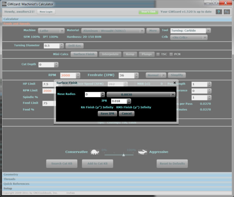
Lathe Surface Finish For turning operations, you can pop up a surface finish box to determine feedrates based on desired surface finish given a particular cutter nose radius.
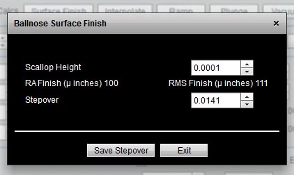
Mill Surface Finish for Ballnose 3D Contouring If you've selected a mill for your machine and ballnose geometry for the cutter, the Surface Finish mini-calc will help you determine stepover for a particular surface finish:
Ramping
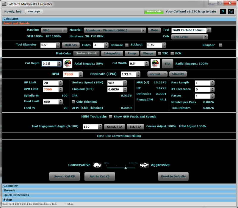
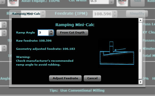
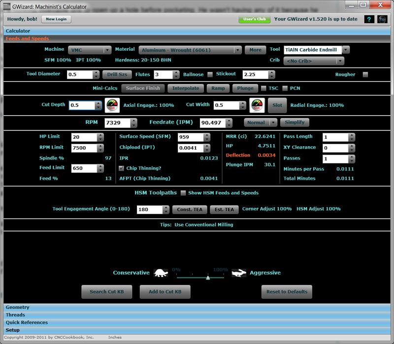
Initial scenario for ramping... From the screen shot above you can see I've set up an aggressive machining scenario in 6061 aluminum. I've got a 1/2" 3-flute TiAlN Endmill selected and it's a serrated "corncob" rougher to boot. I want to set up my CAM program to cut a pocket on a part, and I've decided my entry to the pocket will be via ramp. I'll show how to use the Ramp Mini-Calc to solve a couple of interesting problems. First, let's say I just plan to ramp down at some "standard" rate, say a 3 degree angle. What should my feeds and speeds be on that ramp? You should adjust your feeds and speeds slightly when ramping because its harder than making a level cut. Let's say we'll be cutting our pocket at a 1/2" depth. Set up for a full slot cut, because the ramp will be descending into bare metal. Let's also set the depth of cut to be the maximum depth of the ramp in one pass. If we need to go deeper to get down to full cut depth, the ramp will zig zag back and forth. I'll use a 1/2" depth of cut at full ramp. Here is the Ramp Mini-Calc with all that keyed in:
Ramping the Cut Down 3 Degrees... As you can see, with a 3 degree ramp, the adjustment in feedrate is pretty minor, from 108.6'ish IPM down to 106. No biggie, in fact we could probably just choose to ignore it unless we're running a really max'ed out feedrate we've determined through trial and error to be right at the ragged edge. What if we want to see what angle is needed to get all the way down the ramp in say 2" of travel? No problem. Set your depth of cut as before to the bottom of the ramp, bring up the Ramp Mini-Calc and press "From Cut Depth". You'll see a new control appear that wants to know the travel length. We're trying to get there in 2", so fill that in:
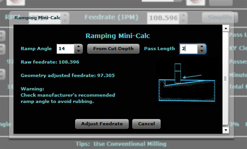
You need a 14 degree angle to ramp down 1/2" in a 2" pass... The Ramping Mini-Calc figures the ramp angle at 14 degrees. This is more aggressive than the 3 degrees we had earlier, so we have to cut our feedrate from 108.6 IPM down to about 97 IPM. That's starting to be worth worrying about in the CAM program. You can just click "Adjust Feedrate" and the Mini-Calc will override G-Wizard's default calculated feedrate based on the new information on ramp angle. This is a probably a good time to mention the warning you see there. Not all cutters can tolerate arbitrary ramp angles. For example, let's say we had a 90 degree ramp angle. That would be a straight plunge. Obviously if you don't have a center-cutting endmill, that's a no-no! Insertable tooling will have a ramp angle limitation that you can find in the manufacturer's catalog. It's often pretty limiting, so be sure you don't find out the hard way you have exceeded it! Interpolated Bosses and Holes What about the Interpolation Mini-Calc? Let's check it out: Suppose you want to use the same basic setup to interpolate a 2" hole. Click on the Interpolate Mini-Calc and here's what you'll see:
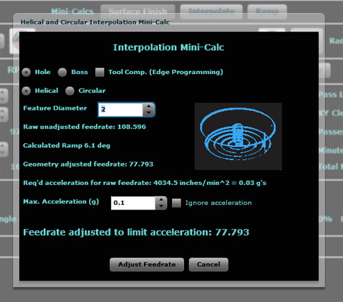
The Helical and Circular Interpolation Mini-Calc... There's quite a bit more going on here as you can see. First, you'll need to specify whether you're machining a hole or a boss. This determines whether the endmill is going around an ID or an OD diameter. In addition, the checkbox tells whether Tool Comp is in use, in which case the toolpath is the cutting edge rather than center of tool. We also need to tell whether we will be doing a Helical Interpolation (going down the hole in a spiral) or a Circular Interpolation (just machine from center out without changing the Z depth). Lastly, we enter our Feature Diameter, which we said would be a 2" hole. Now the Mini-Calc displays a series of intermediate results: - The raw unadjusted feedrate coming in from G-Wizard is 108.6 IPM again. - Since we're doing a Helical Interpolation, there is a ramp angle. We figured it out from the Cut Depth parameter. You could also have used the ramp calculator to go from degrees to cut depth. - We need to adjust for the geometry of both the ramp and the fact that unless we have tool comp on, our feedrate is based on a radius that is either larger (boss) or smaller (hole) than our feature. As we can see, the geometry adjust feedrate is signicantly different in this case, coming in at 77.8 IPM. What's all this business of acceleration? Thought you'd never ask! Not long ago I was chatting with a moldmaker about the pros and cons of interpolation versus a honking indexable drill to open up a hole before pocketing. He wasn't having any of it because he needed a bunch of hole sizes in his molds and he needed them to be done accurately via interpolation. And, he wanted G-Wizard to do the interpolation calculations, and BTW, the feedrates it was giving him were too fast for his machine to interpolate accurately (I related the story in more detail in a prior blog post). After thinking about the issue for quite some while, I finally realized the answer to the accuracy issue was in figuring out the acceleration required for the op and making sure it was within the machine's capabilities. As you can see, the operation depicted by the screen shot requires 0.03 g's of acceleration, which is 4034.5 inches per minute per minute. That's not very challenging for most machines. A high-end machine purpose-built for HSM with linear servos may be able to do 5 g's of acceleration. The vast majority of machines are only capable of a tiny fraction of that kind of performance. You can check your manufacturer's specifications, but I have more bad news--the exact acceleration capabilities can vary fairly significantly from one machine to the next, particularly if they're not right off the assembly line. The thing to do if you want to be able to interpolate holes and other features accurately is to measure your machine's capability in this regard. Mastercam has a document out that walks through how to go about this with their software. Or, you can use G-Wizard's Interpolation Mini-Calc to figure it out. Here's how: 1. Pick a test diameter. Smaller is better because its easier to generate higher accelerations going round and round real fast in a little hole! 2. Set up the Interpolation Mini-Calc for circular interpolation on your small hole. 3. Now go run tests on your machine until you've figured out the fastest feedrate that interpolates that hole accurately. Plug that feedrate into the Mini-Calc and it'll tell you how many g's that was. Write that down! Eventually I will add a field to the Machine Profiles in G-Wizard so it'll remember it for future interpolation calculations. Just as an example, let's say we machine 1/2" bosses with a 1/4" EM. I like bosses for these tests because we can get a micrometer on one to accurately measure it. Holes are more trouble. Given a Cut Depth of 0.2" and a 15% of diameter Cut Width for that boss, G-Wizard has us going round and round at 178 IPM on our 7500 rpm limited spindle. That gives us an acceleration of 0.3 g's. Believe it or not, that's probably heading into the pain threshold for an older VMC that doesn't have the swiftest rapids in the Wild West. So let's say we wind up having to slow it down to 120 IPM before we hit our tolerances. With just a little fiddling in G-Wizard around the Interpolation Calculator, we discover that means our limit is 0.15 g's. If you're just hogging a hole to get a pocket started, don't sweat the acceleration limits. There is a checkbox to turn the feature off. Incidentally, going around a corner on a toolpath will be subject to the same kinds of acceleration limits. You'll want to map these limits out for a couple of hole sizes to see how stable they are for your machine. Keep careful notes, they'll come in handy when you're trying to dial in that high dollar job. Plunge Roughing Plunge Roughing is an extremely effective roughing strategy for cases where rigidity is limited. This can be because the machine is light or because the reach needed is very long. In Plunge Roughing, we mill straight down. One could regard chain drilling with a cleanup pass as an early form of plunge roughing. These days, we can plunge rough with twist drills, but it works better with milling cutters as the drills don't like partial holes. Let's say we have to mill a small pocket that is 2" deep. Moreover, the geometry is such that this has to be done with a 1/2" endmill. That's a recipe for rigidity problems as we can see when we first dial it up in G-Wizard:
Deflection is huge with a 2.25" stickout on a 1/2" endmill... The deflection is huge--0.0034". It's tough to deal with a 2.25" stickout on a 1/2" EM, even though we're only cutting 1/2" deep per layer. If we run the Cut Optimizer and lock both Cut Width and Cut Depth, it wants to back the feed off all the way to 25 IPM to get rid of the deflection. Let's try Plunge Roughing:
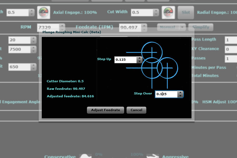
1/8" by 1/8" stepover gives us an 84 IPM feedrate... The Plunge Roughing Mini-Calc wants 2 parameters: "Step Up" and "Step Over". Think of the operation as creating a matrix of plunges. "Step Up" is the hole separation in the Y axis and "Step Over" is the separation on the X. In truth, you could reverse those, it simply wants an idea of your stepover in two directions. We've chosen 1/8" for this operation. In that scenario, we can run an adjusted feedrate of 84.6 IPM, and if we click "Adjust Feedrate" it'll punch that back into Feeds and Speeds as an override. Note that the Plunge Rough feedrate is a little slower than the Non-Plunge. Most cutters are not dedicated Plunge cutters and won't cut quite as fast that way. It's okay though--we're still way ahead because we don't have to slow down to 25 IPM to get rid of tool deflection. Why is deflection not a problem for plunge? Think of a pencil. Stand an unsharpened pencil vertically on a surface plate and try to break it by pressing down. It's darned difficult! But anyone can break a pencil in half by turning it sideways. With Plunge Roughing, the forces are concentrated along Z instead of X and Y. It's a much more rigid dimension. How should you pick Step Up and Step Over? There are a lot of schools of thought on it. G-Wizard's Plunge Roughing calculations work by starting from a normal plunge rate and giving credit for how much the cut is "unshrouded". If the holes are just touching (tangent), it's just a hole and you have to run a normal plunge rate, which is quite slow. The closer together the holes, the more the unshrouding, the better the chip clearance and cooling, and the faster we can go. It's worth noting that entry needs to be handled differently than after you've started plunging along. The first hole has no others around it, and hence no clearance. Run it as a normal hole and not at the Plunge Rough feedrates!
Still looking for faster, better, cuts? Check out our Cutting Knowledge Base, a tool you seldom see except on the most expensive CAM programs...
|
||||||||
|
|
|
|
|
Resources |
Workshop
|
||
|
|
|
|||||||


